Document Number 481.093 Rev. A - 06/04
15
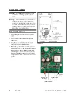
Install the Inside Case
Note:
Refer to Figure 16.
1. Slightly wiggle and push the inside
case assembly over the lock
cylinder assembly, past the lever
catch and against the door.
Note:
Ensure that the solenoid cable
is not pinched and is routed
through the cable clip.
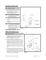
2. Install the two top long mounting
screws.
3. Install the four bottom short mount-
ing screws.
Note:
A Torx security screwdriver bit
can be ordered as part number
404050. A Torx security
screwdriver bit is supplied with
the optional Drill Guide Jig,
part number 404044.
Attach the Inside Lever
Note:
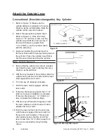
Refer to Figure 17.
1. Push the inside lever onto the lock tube.
Slightly wiggle and push the inside lever until
the lever engages the lever catch.
2. If the door thickness is greater than 1 1/2”
(38mm), the attachment of the inside lever is
complete and you can proceed to the “Attach
the Outside Lever” section. If the door thick-
ness is 1 1/2” (38mm) or less, go to Step 3.
3. Insert the lever release tool into the lever hole
closest to the door. Push in the lever release
tool.
4. While pushing in the lever, allow the lever to
move to engage the lever catch. This second
catch point ensures that the end of the lever is
less than 1/2” (13mm) away from the door as
required by many building codes.
Figure 16
Figure 17
LONG MOUNTING
SCREWS
SHORT MOUNTING
SCREWS
Installation
Содержание PowerLever 1550
Страница 1: ...PowerLever Door Lock Series INSTALLATION GUIDE Models 1550 4550 4560 PROX 9000 ...
Страница 4: ...SPECIFICATIONS 22 Electronic Specifications 22 Hardware Specifications 22 TROUBLESHOOTING 22 ...
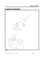
Страница 7: ...Document Number 481 093 Rev A 06 04 3 Figure 1 Parts Check PARTS CHECK Illustrated Parts Breakdown ...
Страница 28: ...Document Number 481 093 Rev A 06 04 24 ...
Страница 29: ...NOTES ...
Страница 30: ......
Страница 31: ......

