background image

TABLE OF CONTENTS

E-PLEX 3x65 Deadlatch/Exit Mortise Model
E-PLEX 3x66 Deadbolt/Swing Bolt Mortise Model

This lock is designed to function with new or existing Adams Rite

®

Hardware

for Deadlatch, Deadbolt, and Exit applications. These Adams Rite Hardware

models (1850, 1950, 4500, 4700, 4900, MS1850S, MS1950S, and 8400 Series)

are sold separately. The specific applications for this model are for narrow stile

aluminum and glass doors, 2” minimum width and 1

3

4

” thick.

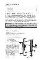
Shipping Package Includes (See Figure 1):

• (1) E-Plex 3x00 Lock Assembly

• (1) Outside Lever (Lever Model Only)

• (1) Screw Pack

• (1) Battery Housing with four AA Batteries (alkaline)

• (2) Keys (Schlage C or Kaba 90 Keyway)

• Documentation pack consists of:

(1) Installation Instructions (this manual)

(1) Operations Manual

(1) Lock Set-up Guide

(1) Quick-Reference Guide

a. 54579–Upper Mounting Screws (2)

b. 44229–Mounting Bushings (4)

c. 54275–Lower Mounting Screws (2)

d1. 75271–Kaba Cam Plug Deadlatch (1)

d2. 75262–Kaba Cam Plug Deadbolt (1)

e1. 75272–Lock Assembly for Lever (1)

e2. 75273–Lock Assembly with Thumbturn (1)

f. 54725–Pinned Torx Screw (2)

g. 34298–Lever Cap (1)

h. 34309–Lever (1)

i. 44226–“D” Bushing (2)

j. 54685–Battery Pack (1)

k. 24554–Battery Cover (1)

l. 54725–Pinned Torx Screws (1)

Tools Required . . . . . . . . . . . . . . . . . . . . . . . . . . . . . . . . . . . . . . . . . . . . . . . . . . . . . . . . . . . . . . . . .3

A.

Door Preparation - Remove Existing Outside Hardware . . . . . . . . . . . . . . . . . . . . . . . . . .3

B.

Stile Preparation . . . . . . . . . . . . . . . . . . . . . . . . . . . . . . . . . . . . . . . . . . . . . . . . . . . . . . . . . . .5

C.

Lock Preparation . . . . . . . . . . . . . . . . . . . . . . . . . . . . . . . . . . . . . . . . . . . . . . . . . . . . . . . . . . .6

D.

Lock Installation . . . . . . . . . . . . . . . . . . . . . . . . . . . . . . . . . . . . . . . . . . . . . . . . . . . . . . . . . . .13

E.

Standard Operations Procedures . . . . . . . . . . . . . . . . . . . . . . . . . . . . . . . . . . . . . . . . . . . . .15

a

Figure 1

c

e1

e2

d1

d2

j

k

l

h

i

g

f

b

2

WARNING:

This lock is designed to be used with Adams

Rite

®

brand hardware only. Improper use or installation of

this product will void the warranty.

LEVER

L

OCK

ONL

Y

Содержание E-PLEX 3X00 SERIES

Страница 1: ...INSTALLATION INSTRUCTIONS E PLEX 3X00 SERIES NARROW STILE LOCK ...

Страница 2: ... of 1 Installation Instructions this manual 1 Operations Manual 1 Lock Set up Guide 1 Quick Reference Guide a 54579 Upper Mounting Screws 2 b 44229 Mounting Bushings 4 c 54275 Lower Mounting Screws 2 d1 75271 Kaba Cam Plug Deadlatch 1 d2 75262 Kaba Cam Plug Deadbolt 1 e1 75272 Lock Assembly for Lever 1 e2 75273 Lock Assembly with Thumbturn 1 f 54725 Pinned Torx Screw 2 g 34298 Lever Cap 1 h 34309 ...

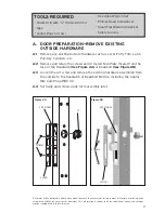
Страница 3: ...latch See Figure 2A or Deadbolt See Figure 2B A 3 Loosen the set screw and remove the existing hardware assembled from the outside to the Deadlatch or Deadbolt Mortise including the Adams Rite Cam Plug 4580 d A 4 Set Scalp and screws aside for reassembly later Figure 2A d 3 set screw scalp screws Figure 2B set screw Disclaimer While reasonable efforts were made to ensure the accuracy of this docum...

Страница 4: ...supplied component part is substituted with a foreign part If the lock is used with a wall bumper the warranty is null and void If a doorstop is required we recommend the use of a floor secured stop The environment and conditions of use determine the life of finishes on Kaba Access Control products Finishes on Kaba Access Control products are subject to change due to wear and environmental corrosi...

Страница 5: ...e of the door stile Ensure the pins from the Cam Plug are through the proper holes the tem plate is straight and aligned with the edge of the door and that TOP is facing up and BOTTOM is facing down See Figure 3 B 3 With a center punch or awl mark the four drilling points B 4 Utilizing a power drill with 3 8 drill bit drill four holes as marked completely through the door interior and exterior of ...

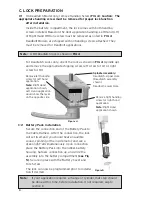
Страница 6: ...ht Hand application shown Left Hand application would show the lever on the opposite side Remove right handing screw for right hand application Note Right Hand application shown Spindle Assembly Deadlatch Upper Hole Deadlatch assembly shown Deadbolt Lower Hole C 2 Battery Pack Installation Secure the connection end of the Battery Pack to the Cable Harness After the connection the lock will set its...

Страница 7: ...S CONTROL 2941 INDIANA AVENUE WINSTON SALEM NC 27199 3770 NO POSTAGE NECESSARY IF MAILED IN THE UNITED STATES BUSINESS REPLY MAIL FIRST CLASS MAIL PERMIT NO 1563 POSTAGE WILL BE PAID BY ADDRESSEE WINSTON SALEM NC ...

Страница 8: ...r Exercise Room This lock is New Installation Replacing a conventional keyed lock Replacing a Kaba Mechanical Pushbutton Lock Replacing a Kaba Electronic Access Control Replacing a Keyless Lock other than Kaba How did you learn about Kaba Access Control Pushbutton Locks Advertisement Previous Use Internet Web Another Use Locksmith Maintenance Training Class Other please specify What was your reaso...

Страница 9: ...9 Notes ...

Страница 10: ...10 Notes ...

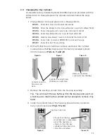
Страница 11: ...e the existing cylinder from the housing assembly Tip You can insert the key half way into the key way and use it as a tool to aid in rotating the cylinder out far enough to remove it by hand 4 Inside the cylinder hole of the housing ensure the Key Override Cam is positioned clear Fig s 9 10 Ensure that the Key Override Cam is completely out of the opening as shown so that the key cylinder will be...

Страница 12: ...n of the cylinder by holding the cylinder in place and rotating the key 90 degrees clockwise The Lever or Thumb Turn should be able to freely move as if you were opening a door Return the key to its original position and remove Attempt to rotate the Lever or Thumb Turn The lock should remain secure 9 If lock performs adequately secure cylinder in place with the original cylinder locking screw Scre...

Страница 13: ... lock towards the face of the stile until the two pins of the Cam Plug mate into the two holes of the lock mounting plate D 3 From the Screw Pack place two Mounting Plate Bushings b into the lower interior 3 8 holes D 4 Secure the upper portion of the lock to the stile with two 10 24 x 2 3 8 screws a inserting the screws directly into the upper portion of the lock D 5 From the screw pack place the...

Страница 14: ... Allen wrench See Figure 16 D 8 Check for proper operation of the lock using thumbturn lever with key in override cylinder turned to the three o clock position Once smooth lock operation is verified tighten cam adjustment screw on mortise face and re install Adams Rite Scalp with 2 or 3 screws D 9 Before closing the door refer to Section E Standard Operating Procedures to ensure proper function a ...

Страница 15: ...t Master PIN access code by depressing the appropriate code buttons With each button depression you should hear a short audible beep and see a green light at the top right of the number pad Once the last button in the code is depressed you will hear a longer audible beep and internal motor action releasing the locking device At this point you have 5 seconds to retract the latch or the lock will ti...

Страница 16: ...Kaba Access Control 2941 Indiana Avenue Winston Salem NC 27105 USA Tel 800 849 8324 336 725 1331 Fax 800 346 9640 336 725 3269 www kabaaccess com www e plexlock com PKG3215 1107 ...

Отзывы: