background image

8

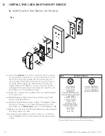
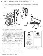
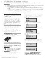
E-730/630/750/79E/ RT Series Installation Guide - PK3677_T_04_16

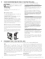
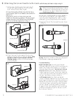
Activate the panic bar. The latch bolt or rod 

retracts fully.

Turn the outside lever downward. The latch bolt 

or rod does not retract.
If the latch bolt or rod retracts, verify that 

the batteries are properly installed.
If the lever feels tight (hard to turn, or does 

not return easily to its horizontal rest position), 

check the spindle length vs. the door thickness 

(the spindle may be too long). Check that the 

slotted end of the spindle is inserted in the lock 

housing hub, not the exit device.

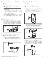
Test the lock’s response to keycards: a Test key-

card, a Grand Master keycard, and an Emergency 

keycard. 
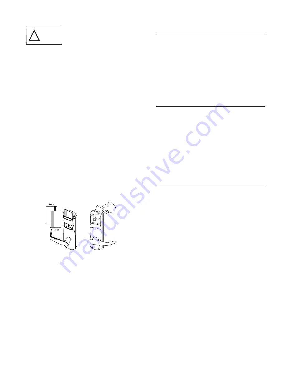
Insert keycards as shown below, with the mag-

netic stripe facing toward the door and to the 

left. For 79E, present cards to reader.

A  Test the Lock Before Programming

Normal Entry: Use the Test keycard with the 

reader. The 

red

 and 

green

 LEDs each flash once 

and then the 

green

 LED flashes for four sec-

onds. 
Turn the outside lever downward while the 

green

 LED is flashing. The latch or rod retracts 

fully. Release the lever, then turn it again. The 

latch or rod must not retract after the LED 

stops flashing without first inserting the 

keycard .

B  Lock Programming

Program the lock with its Common Area number 

(exit devices are usually programmed as common 

areas, see Reference Manual).
Use the Grand Master keycard with the reader. 

The 

green

 LED flashes. Turn the outside lever 

downward while the 

green

 LED is flashing. The 

latch or rod retracts fully and the LED stops 

flashing after 4 seconds. Release the lever, 

then turn it again. The latch or rod must not 

retract again without first inserting the 

keycard .

C  Emergency Keycard Access

Use the Emergency keycard with the reader. 

The 

green

 LED flashes for 4  seconds. Then, turn 

the outside lever downward. The latch or rod 

retracts fully .

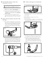
While standing outside the room, close the door 

and ensure that it is  properly latched. Open the 

door using the Grand Master keycard using the 

same procedure.

Caution! Perform the following procedures 

in order, with the door OPEN unless other-

wise indicated.

!

FDU

Program the lock using the FDU and the 

E-760/770/790 communication cable (see 

Reference Manual). If this is not a new installation 

but a replacement of a single lock or a group of 

locks in a property already equipped with the Kaba 

Locking system, transfer the security informa-

tion from a neighbouring lock to the new lock by 

using the Reset Addresses function (see Reference 

Manual resetting lock addresses). 

ATLAS

Program the lock using the M-Unit (Maintenance 

Unit). Refer to ATLAS User Guide.

I

n the case of a replacement lock resetting the 

addresses will ensure that all past lost and stolen 

keycards remain cancelled in the new lock and will 

set the addresses for the Section, Floor, Group, 

Zone and Area sub-master level so that staff key-

cards in use at the property will have the same 

pattern of access to the door as before. This step 

makes the lock replacement transparent so that 

the new lock accepts and rejects the same key-

cards as the old lock.

Multihousing

Program the lock using the M-unit or EAMU FDU.. 

Refer to RezShield User Guide or FDU user Guide.

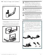
1

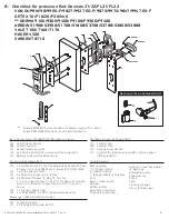
  Panic Bar

2

  Outside Lever

3

  Electronics and Card Reader

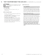
 TEST THE OPERATION OF THE E-730/750/79E LOCK


(For 630 lock go to Section H) (For RT lock series, please refer to system 6000 manual)

 PROGRAM THE E-730/750/79E LOCK


(For 630 lock go to Section H) (For RT lock series, please refer to system 6000 manual)

Содержание E-730 Series

Страница 1: ...INSTALLATION GUIDE Exit Device Operators Generation E 730 630 750 79E RT Series E 730 Series 630 Series 750 Series 79E RT Series...

Страница 2: ...G Operating the Emergency Override 9 H Test the operation of the 630 Lock 10 J Installing the Mechanical Override 11 Parts and Tools List 11 1 Upon unpacking the Lock 12 2 Preparing the Outside Housin...

Страница 3: ...des S Double enclosure T 2 X Pan Head Screws 8 32 X 1 2 Tools Required Safety glasses 5 16 7 9mm drill bit 1 2 13mm drill bit 1 25mm drill bit or hole saw Drill Awl or center punch Hammer Rubber malle...

Страница 4: ...p See Drilling Template 2 or 4 Holes Backset Vertical Line Inside of Door 4 Position the drilling template attached in this book let on the inside of the door aligning the door handle height mark and...

Страница 5: ...orizontal rest position appropriate to the handing of the door as shown Simply push the lever onto the tube until it clicks in place If more force is required to engage the handle use a rubber mallet...

Страница 6: ...Adaptor Plate E using 2 screws or 4 screws H depending on the Exit Device For Detex only use 2 or 4 Flat washers Q 4 5 Make sure the lock and the Exit Device are well aligned and then tighten screws 4...

Страница 7: ...and re inserted if oriented incorrectly Choose a spindle that engages by 1 8 minimum in the exit device chassis and that it is not too long to bottom out against the exit device mecha nism to jam the...

Страница 8: ...st inserting the keycard C Emergency Keycard Access Use the Emergency keycard with the reader The green LED flashes for 4 seconds Then turn the outside lever downward The latch or rod retracts fully W...

Страница 9: ...ect the Programming Menu then press Program 1 A lock 2 Another FDU 4 Wait 2 seconds Enter 1 to select the Lock option and press Enter Function 1 Program Addresses 2 Reset Addresses 5 Enter 7 to select...

Страница 10: ...s a day before today and finishes at least one day after installation testing date in order to avoid check in check out time periods B Code entry and access Enter the user code to validate complete lo...

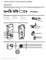
Страница 11: ...scewdriver less that 1 8 A Lock housing B Inside drive hub C Nylon washer D Spring washer Not for lever feel E Drive tube F Lever catch G Countersink H Lever handle I Cap J Cylinder K Cylinder plug L...

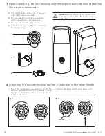
Страница 12: ...Assemble the lever cylinder and lock components before affixing the entire unit to the door A The small indents on the cross of the over ride shaft in line horizontally B The nylon washer and the spri...

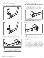
Страница 13: ...l not work Fig 6 countersink in the top position Fig 7 countersink in the bottom position 3 Insert the cylinder into the lever handle see Fig 3 4 Put the cylinder plug into the lever see Fig 4 5 Makin...

Страница 14: ...turned If it does it was not assembled correctly as shown in step 4 Fig 6 7 Release the lever handle Insert the small screwdriver T page 10 into the small hole on the underside of the lever handle and...

Страница 15: ...ess Step 6 Very Important To verify that the lever handle has been correctly attached to the housing Fig 11 16 Without using the key turn the lever handle clockwise for Right handed locks or coun ter...

Страница 16: ...above operation turn key clockwise until it stops latch and deadbolt must retract complete ly Verify the functionality of the override after the lock is installed on the door Fig 16 Fig 17 23a Loosen...

Страница 17: ...h the key card or key override Do not close the door until you are certain that you have installed the unit correctly Note The lever handle must stay in the hori zontal position when turning the key d...

Страница 18: ...ference by one or more of the following measures Reorient or relocate the receiving antenna Increase the separation between the equipment and receiver Consult the dealer or an experienced radio TV te...

Страница 19: ...19 E 730 630 750 79E RT Series Installation Guide PK3677_T_04_16...

Страница 20: ...468 3555 1 514 340 9025 Saflok 1 800 999 6213 1 248 837 3700 General Information www kabalodging com Online Consumable Orders www ilcostore com www saflokstore com To access all of our easy steps ple...

Отзывы: