V I
INSTALL THE LOCK
7 1 0 - I I / 7 4 0 S E R I E S I N S TA L L AT I O N G U I D E • P K 2 7 1 0 / 0 8 / 0 2
P a g e 8
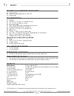
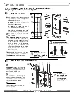
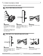
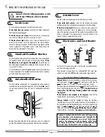
On the rear housing, rotate the override cam
using a flat-head screwdriver, until the indicator
mark corresponds with the handing of the door
(L for LH/LHR or R for RH/RHR).
3.
For wood doors only,
install the tube (F) in the bottom hole in the door.
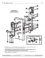
4. Insert one square spindle (E) into each of the inside and outside mortise hubs (G). For lever models, install the long spindle and for
knob models, use the short spindle. Then insert one compression spring (D) into each of the inside and outside handles (X).
5. Thread the cable(s) from the outside housing through the top hole in the door. The electrical override model has two cables (H and
U), mechanical override models have one (H).
6. Gently pull the cables through the door, and position the outside housing on the door, ensuring that the mortise spindle (E) engages
the lever handle (X1).
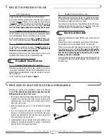
7. Connect the outside housing cable (H) to the female socket (K) on the inside housing. A plastic keycard can be used to push the
connector into place for a snug connection.
8. Connect the mortise cable (I) to the connector (J) on the inside housing.
9.
On electrical override models,
connect the override cable (U) from the outside housing to the connector (V) on the inside housing.
10. Fold excess cables inside the door, and position the inside housing on the door without pinching cables. Ensure the lever handle (X2)
engages the mortise spindle (E), and the thumbturn spindle (W) engages the mortise. On mechanical override models, ensure the
override cylinder tailpiece (Y) engages the override cam (S) on the inside housing.
11. Secure both housings to the door using two of the four 10-24, 1/8" hex-head screws (Q), on the bottom right and top left of the
inside housing.
12. Turn the outside lever and then the inside lever to ensure that the bolt retracts.
13.
For mechanical override models,
the override key has been sent to the manager. Test the override in the manager's pres-
ence. Turn the key 2/3 of a rotation (clockwise for a left-hand lock, and counterclockwise for a right-hand lock). The cylinder and
the inside lever rotate freely, and the latch bolt retracts fully. If the override cylinder does not rotate freely, the cylinder tailpiece (Y)
is too long and must be shortened. If the override cylinder rotates freely but does not operate the lock mechanism, the tailpiece may
have been cut too short, requiring replacement.
14. Install the two remaining mounting screws (Q) and check the alignment of the lock and mortise (or latch) mechanisms by operat-
ing the lever handles, the latch, the deadbolt and the thumbturn. A properly aligned lock allows the smooth return of the thumbturn
to its original position.
15.
For mechanical override models,
test the mechanical override mechanism again.
16. For wood doors, install the #6 x 1" (25mm) screw (P) through the hole in the battery compartment portion of the inside housing.
1
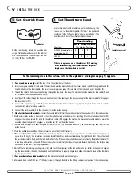
Set Override Hand
For mortise models with a thumbturn on the inside housing, the
groove on the thumbturn spindle (W) must be positioned
according to the following table prior to installation. (The
thumbturn must be in the vertical position as shown.)
Door Handing
RH
LH
RHR LHR
Mortise
Thumbturn Position
AMM (standard or
R
L
R
L
auto-deadbolt)
SMM
L
R
L
R
If there is no groove on the thumbturn or R/L marking
on the inside housing, the orientation is not important.
Simply ensure the thumbturn is vertical.
2
Set Thumbturn Hand
indicator
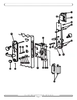
For the remaining steps in this section, refer to the exploded view diagram on page 9, opposite.
thumbturn vertical
align groove with
correct mark
W


