pin 1
1
2
3
4
5
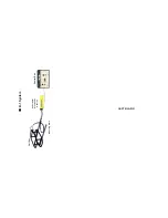
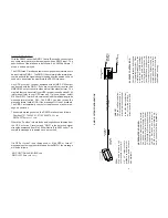
Enlarged front view of 5 pin
connector . Pin 2,3 and 5
not used.(PIN END)
fish 1
white
ground
black + shield
pin 4
Analog output (0-5vdc)
Pin 2,3, and 5 Not used
2
1
3
4
5
5 pin socket
in box
5 pin DIN
Connector
in RMD-1
Control Box
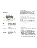
REMOTE METAL DETECTOR DESCRIPTION
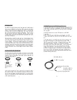
The RMD-1 system employs two coils molded into rugged ABS
shells and firmly attached to the underwater vehicle with a corrosive-
proof tubular PVC frame. The frame provides a sturdy mount and
keeps the coils far enough away from the ROV so as not to be
affected by the metal parts. The oval coils produce a detection
envelope which extends 3 to 5 feet into the bottom. The sleek, low
profile coil design minimizes drag and weight on the ROV.
When the coil senses metal it sends a signal to the RMD-1
"downstairs" electronics unit attached to the underwater vehicle.
This downstairs electronics unit can produce RS232 output , O-5 vdc
output, or a proprietary signal used by the JWF topside control/
readout unit. The output from the downstairs electronics unit can
be transmitted through the ROV's umbilical or a separate cable.
The standard RMD-1 has a topside Control Box which displays the
readout with both a meter and audio alarm. The closer the proximity
of the metal target, the stronger the reading. The topside unit can use
the underwater vehicle's umbilical cable to supply voltage to the
downstairs electronics unit and to receive the output signal from the
downstairs unit. The RMD-1 can be powered from 120 vac (stan-
dard) or 220 vac, or 9 - 36 vdc.
The RMD-1 is easy to operate and readily attaches to most any
underwater vehicle.
COIL SIZES
The detection range of a pulse metal detector is determined to some
degree by the coil size. Larger coils will detect large targets deeper,
but have less sensitivity to the smaller targets. The 10 in x 16 in x 5
in coil, which is standard on the RMD-1, is an ideal size for detecting
both small targets, such as individual coin size objects, and larger
targets to 5 ft deep. Special coil sizes can be built for special
applications.
ANALOG OUTPUT OPTION
The analog output option allows the RMD-1 to be connected to an
external device such as a strip chart recorder or data logger. The
output is 0 to +5.00vdc. The voltage is a representation of the
detection signal strength.
The analog output uses 2 wires and is wired to a 5 pin DIN connector
on the RMD-1 as Follows:
RS232 WIRING
J
W
F
I S
H E
R
S
M
F
G
I N C
B
E R
K L
E Y ,
M A
0
2 7 7 9
6 5 A N
T H
O N
Y S T
V
I S
U
A L
D E
T E
C
T
I O
N
D
I S
P
L
A Y
P
O
W
E
R
A
U
D
I O
J
W
F
I S
H E
R
S
M F
G
I N C
B
E R
K L
E Y ,
M A
0
2 7 7 9
6 5 A N
T H
O N
Y S T
V
I S
U
A L
D E
T E
C
T
I O
N
D
I S
P
L
A Y
P
O
W E
R
A
U
D
I O
2
13
5 pin DIN
Connector
in RMD-1
Control Box
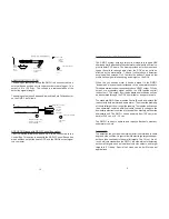
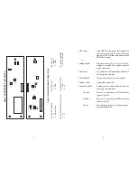
RS232
White
Black and Shield
RS232
Interface
9 pin "D"
female
connector
pin 2
pin 5
Pins 2,4 and 5 Not used
5 pin socket
in box
1
2
3
4
5
3
Enlarged front view
of 3 pin connector
(PIN END)
1
2
5
2
END VIEW
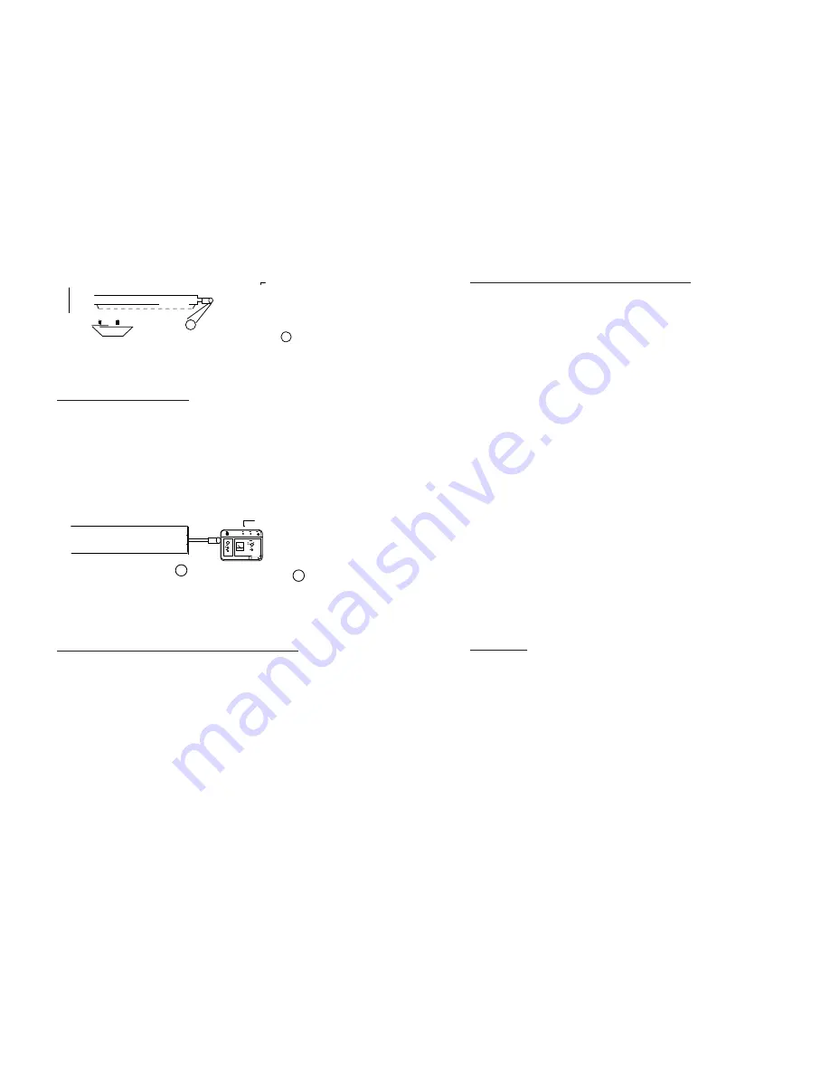
GPS OPTION (used with RS232 Control Box option)
The GPS option allows the boat's GPS to be connected to the
Control Box. This option is used with the RS232 Control Box option
which will then output the boat's GPS and the RMD's output signal
to a computer.


