1-4
UX-V30
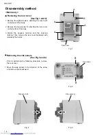
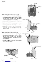
Remove the eight screws A attaching the rear cover
on the back of the body.
Remove the two screws B attaching the rear cover
on the bottom of the body.
Unlock the speaker terminal and the antenna
terminal, then remove the rear cover backward with
releasing the hooks.
1.
2.
3.
Disassembly method
<Main body>
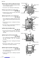
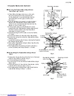
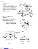
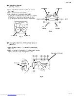
Removing the rear cover
(See Fig.1 and 2)
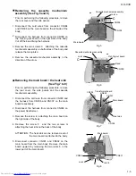
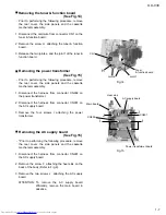
Prior to performing the following procedure, remove
the rear cover.
Move the side panels in the direction of the arrow
and remove them backward.
1.
Removing the side panels
(See Fig.3 and 4)
Fig.1
Fig.2
Fig.3
Fig.4
Rear cover
A
A
A
A
A
Rear cover
B
B
Side panel (L)
Side panel (R)
Содержание UX-V30
Страница 31: ...1 31 UX V30 LC75342 ...
Страница 34: ...1 34 UX V30 MEMO ...
Страница 35: ...2 1 UX V30 I H A B C D E F G 1 2 3 4 5 6 Block diagram ...
Страница 39: ...2 5 UX V30 I H A B C D E F G 1 2 3 4 5 6 Tuner circuit UX V30 FM TUNER MAIN SIGNAL AM SIGNAL ...
Страница 42: ...2 8 I H A B C D E F G 1 2 3 4 5 6 UX V30 UX V30 Printed circuit boards Main board ...
Страница 43: ...2 9 UX V30 I H A B C D E F G 1 2 3 4 5 6 Micon P C board ...
Страница 44: ...2 10 I H A B C D E F G 1 2 3 4 5 6 UX V30 UX V30 CD board ...
Страница 45: ...2 11 UX V30 I H A B C D E F G 1 2 3 4 5 6 Tuner P W B ...
Страница 46: ...2 12 I H A B C D E F G 1 2 3 4 5 6 UX V30 UX V30 MEMO ...
Страница 48: ...UX V30 3 2 MEMO ...


