background image

EXIT

PHASE

CHROMA

BRIGHT

CONTRAST

MENU

VOLUME/SELECT

+

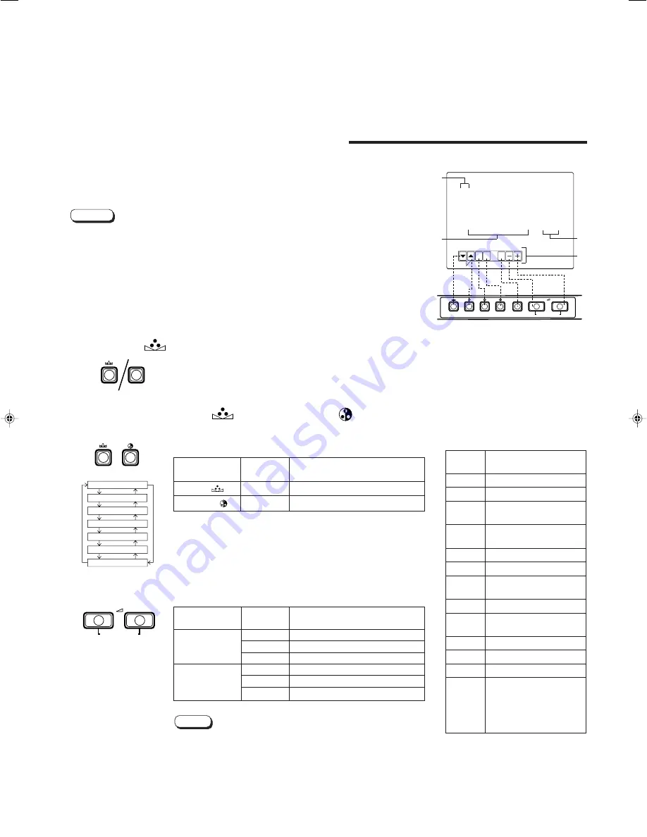
DISPLAY AND SELECTIONS IN THE <SET-UP
MENU> MODE (SETTING)

• H. POSITION

• CONTROL LOCK

• ASPECT REMOTE

• V. POSITION

• STATUS DISPLAY

• WHITE BALANCE

• INPUT REMOTE

You can set the following set-up menu items.

1. While pressing the MENU button, press the

PHASE ( 

 ) button.

The <SET-UP MENU> screen is displayed.
* The screen automatically disappears when no operation is

performed after about 5 minutes.

2. Press the PHASE ( 

 ) or CHROMA ( 

 ) button

to select the desired menu item.

A selection mark (

3

) is put next to the selected item.

MENU

PHASE

3. Press the VOLUME/SELECT buttons to set.

For the WHITE BALANCE setting, select the CUT OFF or
DRIVE setting screen, then select the buttons (PHASE/
CHROMA/BRIGHT) corresponding to the function indicated
(R/G/B).

Press the EXIT (MENU) button to return to the <SET-UP
MENU> screen.

Notes:

<SET-UP MENU> screen

<Front panel buttons>

1

 Selection mark (

3

): Indicates the

menu item you select.

2

 Menu item: Menu items you can

select.

3

 Setting display: Indicates the

current settings (value).

4

 Function display: The functions of

the front panel buttons (7 buttons
on the left) correspond to the
function displayed.

Function

Contents

displayed

Forward the menu item.

5

Reverse the menu item.

Lower the adjustment
value. (to the minimum)

+

Raise the adjustment
value. (to the maximum)

3

Forward the setting value.

2

Reverse the setting value.

EXIT

Exit the <SET-UP MENU>
screen. (release)

DRV

Selects DRV adjustment.

CUTO

Selects CUT OFF
adjustment.

R

Adjusts red signal level.

G

Adjusts green signal level.

B

Adjusts blue signal level.

DISP

Turns the ON-SCREEN
display on or off. (This
function is effective only
in the DRIVE or CUT OFF
adjustment mode.)

Front panel

Function                     

Contents

button

displayed

PHASE ( 

 )

Forward selection mark (

3

)

CHROMA ( 

 )

5

Reverse selection mark (

3

)

Front panel

Function                     

Contents

button

displayed

+

Increase (to max. value)

3

Forward the setting value

CUTO

Selects CUT OFF setting screen

Decrease (to min. value)

2

Reverse the setting value

DRV

Selects DRIVE setting screen

VOLUME/

SELECT (–)

VOLUME/

SELECT (+)

Parameters for H. POSITION and V. POSITION can be set separately depending on
the video input (Input A (VIDEO) or Input B (VIDEO / Y/C)) selected by the input select
buttons on the front panel.
Select the required video input with the input select buttons on the front panel in
advance.

 WHITE BALANCE can be set individually at 6500 or 9300 for the colour temperature

value.
Set COLOR TEMP. to the value 6500 or 9300 in the <MENU> screen in advance.

Notes:

<SET-UP MENU>

H. POSITION

:    00

V. POSITION

:    00

WHITE BALANCE
CONTROL LOCK

: OFF

STATUS DISPLAY

: ON

INPUT REMOTE

: OFF

ASPECT REMOTE

: OFF

1

2

3

4

PHASE

CHROMA

VOLUME/SELECT

+

9

H. POSITION

V. POSITION

WHITE BALANCE

CONTROL LOCK

STATUS DISPLAY

INPUT  REMOTE

ASPECT REMOTE

Содержание TM-H1375SU - Color Video Monitor

Страница 1: ...omer Use Enter below the Serial No which is located on the rear of the cabinet Retain this information for future reference Model No TM H1375SU Serial No TM H1375SU PHASE CHROMA BRIGHT CONTRAST MENU INPUT SELECT VOLUME SELECT B A POWER _ON OFF UNDER SCAN ...

Страница 2: ...ent or relocate the receiving antenna Increase the separation between the equipment and receiver Connect the equipment into an outlet on a circuit different from that to which the receiver is connected Consult the dealer or an experienced radio TV technician for help PRECAUTIONS Use only the power source specified on the unit 120 V AC 50 Hz 60 Hz Keep flammable material water and metal objects awa...

Страница 3: ... SAFETY PRECAUTIONS 2 CONTROLS AND FEATURES 4 HOW TO HANDLE BASIC OPERATIONS 7 HOW TO USE THE MENU FUNCTIONS 8 HOW TO INITIALISE THE SETTING 11 BASIC CONNECTION EXAMPLE 12 TROUBLESHOOTING 14 SPECIFICATIONS 15 3 ...

Страница 4: ... button INPUT SELECT B Selects the video signal input to the VIDEO B terminal and the audio signal input to the AUDIO B terminal on the rear panel When selected the input B VIDEO Y C indicator lights Note The VIDEO B terminals include a video terminal BNC connector and a Y C terminal mini DIN 4 pin connector The Y C S video terminal is given priority Input A VIDEO button INPUT SELECT A Selects the...

Страница 5: ... AUDIO A VIDEO B VIDEO B VIDEO A VIDEO A ASPECT To AC outlet 120 V AC 50 Hz 60 Hz Video B Y C terminals VIDEO B Y C IN OUT Y C S Video signal input IN and output OUT terminals The output terminal is bridge connected IN Y C separated S video signal input terminal OUT Bridge connected Y C separated S video signal output terminal Notes For corresponding audio signals use the AUDIO B terminals When bo...

Страница 6: ...dio signal output terminal Notes For corresponding video signals use the VIDEO B terminals or VIDEO B Y C terminals Also refer to BASIC CONNECTION EXAMPLE on pages 12 and 13 Remote terminals REMOTE INPUT A B ASPECT Remote terminals for external control Selecting INPUT A or INPUT B and the ASPECT RATIO is available via external control External control is set in the SET UP MENU screen To use extern...

Страница 7: ...TRAST Contrast control PHASE CHROMA BRIGHT CONTRAST POWER ON OFF VOLUME SELECT Screen indication will disappear about 10 seconds after operating About the STATUS indication With the COLOR SYSTEM setting set to AUTO mode when you turn on the power or select inputs the colour system indication appears for about 3 seconds on the screen while NTSC or PAL signals are being detected It does not appear w...

Страница 8: ...is performed after about 5 minutes MENU 2 Press the PHASE or CHROMA button to select MENU items A selection mark 3 is put next to the selected item PHASE CHROMA SHARPNESS COLOR TEMP COLOR SYSTEM ASPECT RATIO 3 Press the VOLUME SELECT buttons to set 4 If you want to set the other menu items repeat procedures 2 and 3 5 Press the MENU button to quit 1 Selection mark 3 Indicates the menu item you sele...

Страница 9: ...um Raise the adjustment value to the maximum 3 Forward the setting value 2 Reverse the setting value EXIT Exit the SET UP MENU screen release DRV Selects DRV adjustment CUTO Selects CUT OFF adjustment R Adjusts red signal level G Adjusts green signal level B Adjusts blue signal level DISP Turns the ON SCREEN display on or off This function is effective only in the DRIVE or CUT OFF adjustment mode ...

Страница 10: ...e front panel will display the message CONTROL LOCK ON on the screen for about 3 seconds The CONTROL LOCK function is maintained even when the power is turned off To turn off the CONTROL LOCK function while holding the MENU button press the PHASE button Then set the CONTROL LOCK function to OFF Even when the CONTROL LOCK function is set to ON the following operations are available Power Switch ope...

Страница 11: ...ry set initial values 1 Press the Power switch to turn the power OFF G The SET UP MENU RESET screen is displayed The screen automatically disappears when no operation is performed after about 5 minutes PHASE MENU POWER ON OFF Initial settings SET UP MENU RESET screen 2 While pressing both MENU button and PHASE button press the Power switch to turn the power ON g 3 Setting 䢇 Initialisation is requi...

Страница 12: ...k This is caused by the same video signal looping between the VCRs and is not a malfunction Select the video input INPUT A VIDEO or INPUT B VIDEO Y C with the INPUT SELECT buttons on the front panel When both VIDEO B terminals are connected input at the same time the Y C terminal is given priority The ASPECT RATIO or INPUT A B settings can be controlled via the REMOTE terminal by setting ASPECT RE...

Страница 13: ...pen circuit Closed circuit open short ASPECT RATIO 4 3 4 3 16 9 16 9 External control functions External control switch closed circuit short open circuit open RCA pin 13 Video Camera Video Monitor VCR Y C S video Y C S video signal cable Audio Audio signal cable Y C S video Y C S video signal cable Audio Audio signal cable REMOTE Remote cable Signal Flow Video Monitor VCR ...

Страница 14: ...e audio signal cable firmly See pages 12 and 13 Move the device away from the monitor until the picture stabilises Set COLOR SYSTEM in the MENU screen to AUTO See page 8 Set each picture control to the standard setting See page 7 Move the device away from the monitor and turn the monitor s power off Wait at least 30 minutes then turn the power on again Set ASPECT RATIO in the MENU screen to 4 3 4 ...

Страница 15: ...ble auto termination AUDIO A 1 line monaural RCA pin x 2 0 5 V rms high impedance bridge connection possible AUDIO B 1 line monaural RCA pin x 2 0 5 V rms high impedance bridge connection possible REMOTE INPUT A B 1 line RCA pin x 1 REMOTE ASPECT 1 line RCA pin x 1 䡲 Audio power output 1 W monaural 䡲 Built in speaker 3 1 8 8 cm round x 1 impedance of 8 Ω 䡲 Environmental conditions Operation temper...

Страница 16: ...ON OFF UNDER SCAN 13 5 8 346 11 1 4 284 12 1 4 310 8 5 8 217 11 3 8 287 14 7 8 375 14 3 8 363 5 1 16 1 5 1 4 5 3 16 3 5 2 5 8 63 7 10 3 4 273 Printed in Thailand LCT0923 001A H 1000 K V JMT 2000 VICTOR COMPANY OF JAPAN LIMITED TM H1375SU COLOR VIDEO MONITOR JVC PROFESSIONAL PRODUCTS COMPANY DIVISION OF US JVC CORP 1700 Vallery Road Wayne NJ07470 JVC CANADA INC 21 Finchdene Square Scarborough Ontar...

Отзывы: