


8
Getting Started
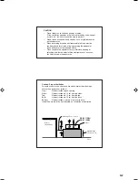
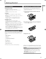
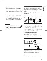
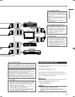
Turn off all components before connections.
Illustrations of the input/output terminals below are typical
examples.
When you connect other components, refer also to their
manuals since the terminal names actually printed on the rear
vary among the components.
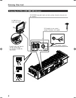
RX-E111R/
RX-E112R
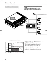
*1 The signals input from a SCART terminal cannot be output
through the same SCART terminal.
*2 The video format of the output video signals are consistent
with that of the input video signals. For example, if S-video
signals are input to this unit, no signals other than S-video
signals can be output from this unit.
Refer to the manuals supplied with the video components to
check the setting of the input/output video signals.
*3 The signals for T-V LINK function are always going through
the unit.
SCART Terminal Specifications
TV
VCR
STB
DVD
AUDIO
L/R
䡬
䡬
䡬
䡬
IN
Composite
䡬
䡬
䡬
䡬
VIDEO
S-video
−
䡬
䡬
䡬
RGB
−
䡬
䡬
䡬
AUDIO
L/R
䡬
*
1
䡬
*
1
OUT
Composite
䡬
*
1
*
2
䡬
*
1
*
2
VIDEO
S-video
䡬
*
2
−
RGB
䡬
*
2
−
T-V LINK
䡬
*
3
䡬
*
3
䡬
*
3
䡬
*
3
FM 75
CO
AX
IAL
CAUTIO
N :
SPEAKER
IMPED
ANCE
8
16
+
–
+
–
+
–
+
–
AM LOOP
AM
EXT
DIGIT
AL 2
(STB)
DIGIT
AL 1
(DVD)
DIGIT
AL IN
CENTER
SPEAKER
REA
R S
PEAKERS
RIG
HT
LEF
T
FRONT S
PEAK
ERS
RIG
HT
LEFT
OUT
(REC)
IN
(PLA
Y)
TAPE
SUBWOOFER
OUT
AUDIO
VCR
TV
DVD
STB
AV
IN/OUT
AV
IN
D
AV IN/OUT
AV IN
VCR
TV
STB
DVD
ANTENNA
EN01-09.RX-E111&112R[B]_f
02.1.17, 9:18 AM
8


