background image

3

English

ANTENNA

AM

EXT

AM

LOOP

FM  75  
COAXIAL

AM

LOOP

ANTENNA

AM
EXT

FM  75  
CO

AX

IAL

AM

LOOP

ANTENNA

AM
EXT

FM  75  
CO

AX

IAL

Getting Started

This section explains how to connect audio/video components and speakers to the receiver, and how to connect the
power supply.

Before Installation

General

• Be sure your hands are dry.
• Turn the power off to all components.
• Read the manuals supplied with the components you are going to

connect.

Locations

• Install the receiver in a location that is level and protected from

moisture.

• The temperature around the receiver must be between –5˚C and

35˚C (23˚F and 95˚F).

• Make sure there is good ventilation around the receiver. Poor

ventilation could cause overheating and damage the receiver.

Handling the receiver

• Do not insert any metal object into the receiver.
• Do not disassemble the receiver or remove screws, covers, or

cabinet.

• Do not expose the receiver to rain or moisture.

Checking the Supplied Accessories

Check to be sure you have all of the following items, which are
supplied with the receiver.
The number in the parentheses indicates quantity of the pieces
supplied.

• Remote Control (1)

• Batteries (2)

• AM Loop Antenna (1)

• FM Antenna (1)

• AC Plug Adaptor (1)

If anything is missing, contact your dealer immediately.

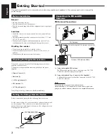
Setting the Voltage Selector Switch

Before connections, always do the following first if necessary.

Set the correct voltage for your area with the voltage selector switch
on the rear panel. Use a screw driver to rotate the switch so the
number the arrow is pointing at is the same as the voltage where you
are plugging in the receiver.

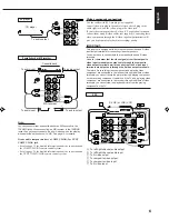
A. Using the Supplied FM Antenna

The FM antenna provided can be connected to the FM 75 

COAXIAL terminal as temporary measure.

B. Using the Standard Type Connector (Not Supplied)

A standard type connector should be connected to the FM 75 

COAXIAL terminal.

Note:

If reception is poor, connect the outdoor antenna.
Before attaching a 75 

Ω 

coaxial cable (the kind with a round wire

going to an outdoor antenna), disconnect the supplied FM antenna.

Connecting the FM and AM
Antennas

FM Antenna Connections

B

FM Antenna

Outdoor FM Antenna Cable

Extend the supplied FM antenna horizontally.

A

VOLTAGE SELECTOR

220V

230


-


240V

127V

110V

Voltage Mark

EN01-09.RX-7001PGD[U,US]/f

00.5.31, 10:53 AM

3

Содержание RX-7001PGD

Страница 1: ...ER VOLUME SOURCE SELECTOR THEATER LIVE CLUB DANCE CLUB HALL PAVILION INPUT ANALOG DIGITAL FM AM TUNING TUNER PRESET TUNER SEA MEMORY FM MODE DVD TV SOUND DBS PHONO TAPE MD VCR FM AM CD SOUND SELECT INPUT ATT BASS BOOST ONETOUCHOPERATION SOURCENAME COMPULINK Remote D I G I T A L STANDBY STANDBY ON RM SRX7001P REMOTE CONTROL CONTROL CHANNEL VOLUME TV VOL STOP PAUSE FF REW VCR TV VIDEO TAPE MD MUTING...

Страница 2: ...completo Qualquer que seja a posição de ajuste do interruptor STANDBY ON a alimentação não é completamente cortada A alimentação pode ser controlada remotamente Warnings Cautions and Others Avisos precauciones y otras notas Advertêcias precauções e outras notas G 1 CAUTION To reduce the risk of electrical shocks fire etc 1 Do not remove screws covers or cabinet 2 Do not expose this appliance to ra...

Страница 3: ... superior Parte trasera 15 cm sin obstrucciones en la parte trasera Fondo Sin obstrucciones colóquelo sobre una superficie nivelada Además mantenga la mejor circulación de aire posible como se ilustra Wall or obstructions Pared u obstrucciones Parede ou obstáculo Stand height 15 cm or more Allura del soporte 15 cm o más Base com altura de 15 cm ou mais Front Frente Frente Floor Piso Piso Precaução...

Страница 4: ... Stations 19 Using the SEA Modes 20 SelectingYour Favorite SEA Mode 20 Creating Your Own SEA Mode 20 Using the DSP Modes 21 Available DSP Modes According to the Speaker Arrangement 23 Adjusting the 3D PHONIC Modes 24 Adjusting the DAP Modes 24 Adjusting the Surround Modes 25 Activating the DSP Modes 27 Using the DVD MULTI Playback Mode 29 Activating the DVD MULTI Playback Mode 29 Using the On Scre...

Страница 5: ...tton 19 s MULTI JOG control Whatthiscontrolactuallydoesdependsonwhich function you are trying to adjust Before using this control select the function by pressing one of the buttons marked with d SOURCE SELECTOR control 10 Remote Control 1 TV CATV DBS button 45 46 2 Source selecting buttons 10 DVD DVD MULTI CD TAPE MD TV DBS PHONO FM AM VCR 3 SURROUND ON OFF button 25 27 4 SURROUND MODE button 25 2...

Страница 6: ... supplied with the receiver The number in the parentheses indicates quantity of the pieces supplied Remote Control 1 Batteries 2 AM Loop Antenna 1 FM Antenna 1 AC Plug Adaptor 1 If anything is missing contact your dealer immediately Setting the Voltage Selector Switch Before connections always do the following first if necessary Set the correct voltage for your area with the voltage selector switc...

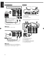
Страница 7: ...nected Connecting the Speakers You can connect the following speakers Two pairs of front speakers to produce normal stereo sound One pair of rear speakers to enjoy the surround effect One center speaker to produce more effective surround effect to emphasize human voices One subwoofer to enhance the bass IMPORTANT After connecting the speakers listed above set the speaker setting information proper...

Страница 8: ...CR You can connect these components using the methods described in Analog connections below or in Digital connections see page 8 Analog connections Audio component connections Use the cables with RCA pin plugs not supplied Connect the white plug to the audio left jack and the red plug to the audio right jack CAUTION If you connect a sound enhancing device such as a graphic equalizer between the so...

Страница 9: ...es not supplied Connecting these video components through the S video input output terminals will give you better picture playback or recording quality IMPORTANT This receiver is equipped with both the composite video and S video input output terminals for connecting video components You do not have to connect both the composite video and S video terminals However remember that the video signals f...

Страница 10: ...the source name which will be shown on the display when selected as the source to DBS See page 13 for details Å To center channel audio output ı To subwoofer audio output Ç To S video output Î To front left right channel audio output To rear left right channel audio output Ï To composite video output VIDEO VIDEO S VIDEO RIGHT LEFT AUDIO VCR IN PLAY OUT REC TV SOUND DBS DVD DVD DVD CENTER SUB WOOFE...

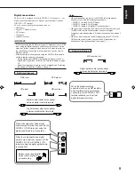
Страница 11: ...lowing components DIGITAL 1 coaxial For DVD player DIGITAL 2 optical For CD player DIGITAL 3 optical For digital TV broadcast tuner When you want to operate the CD player or MD recorder using the COMPU LINK remote control system connect the target component also as described in Analog connections see pages 5 and 6 When you want to operate the DVD player using the AV COMPU LINK remote control syste...

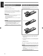
Страница 12: ... connection procedures are complete Do not touch the power cord with wet hands Do not pull on the power cord to unplug the cord When unplugging the cord always grasp the plug so as not to damage the cord Putting Batteries in the Remote Control Before using the remote control put two supplied batteries first When using the remote control aim the remote control directly at the remote sensor on the r...

Страница 13: ...risk the receiver automatically turns on DVD DVD MUILTI CD TAPE MD TV DBS PHONO FM AM VCR IMPORTANT When using the remote control check to see if its remote control mode selector is set to the correct position To operate this receiver set it to AUDIO TV VCR Turning the Power On and Off Standby On the front panel To turn on the power press STANDBY ON The STANDBY lamp goes off The name of the curren...

Страница 14: ...ecting buttons CD TAPE MD PHONO FM AM TV DBS while viewing the picture from a video component such as the VCR or DVD player etc Notes Once you have selected a video source pictures of the selected source are sent to the TV until you select another video source The TV DBS button only works for selecting DBS as the source but not for selecting TV SOUND When you use the DBS tuner change the source na...

Страница 15: ...ction turns on BASSBOOST ON and off BASSBOOST OFF Select BASSBOOST ON to activate the bass boost function The BASS BOOST indicator lights up on the display Select BASSBOOST OFF to cancel it The indicator goes off Note This function affects the front speaker sounds only Attenuating the Input Signal When the input level of the playing source is too high the sounds will be distorted If this happens y...

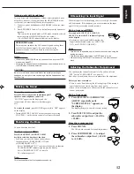
Страница 16: ...inish start from step 1 again On the front panel ONLY 1 Press BALANCE SURROUND ADJUST repeatedly until L R BALANCE appears on the display The display changes to show the current setting AUDIO TV VCR CATV DBS MULTI JOG 2 Turn MULTI JOG to adjust the balance Turning it clockwise decreases the left channel output Turning it counterclockwise decreases the right channel output Changing the Source Name ...

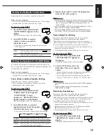
Страница 17: ...ds to 30 cm decrease or increase in distance Rear delay time for Dolby Digital DTS Digital Surround and MPEG Multichannel is to be set to 5 msec When shipped from the factory delay time is set to 5 msec On the front panel ONLY 1 Press SETTING repeatedly until REAR DELAY appears on the display The display changes to show the current setting Setting the Subwoofer Information Register whether or not ...

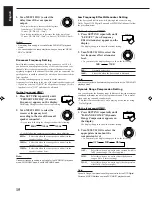
Страница 18: ...r is about 8 cm Note Crossover frequency setting is not valid for the DVD MULTI playback mode 3D PHONIC mode and HEADPHONE mode 80Hz 100Hz 120Hz 0dB 10dB SETTING MULTI JOG OFF MID MAX MULTI JOG Low Frequency Effect Attenuator Setting If the bass sound is distorted while playing back a source using Dolby Digital DTS Digital Surround or MPEG Multichannel follow the procedure below On the front panel...

Страница 19: ... the input mode appears on the display Note Among the sources listed above you can select the digital input only for the sources which you have selected the digital input terminals for See Digital Input DIGITAL IN Terminal Setting 2 Press INPUT ANALOG DIGITAL repeatedly until the digital input mode you want appears on the display Each time you press the button the input mode changes as follows Nor...

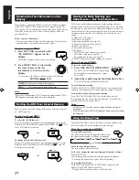
Страница 20: ...using this function you do not have to change the settings every time you change the source The stored settings for the newly selected source are automatically recalled The following can be stored for each source Volume level see page 11 Bass boost see page 12 Input attenuator mode see page 12 Subwoofer output level see page 12 Balance see page 13 SEA modes see page 20 DSP modes 3D PHONIC mode set...

Страница 21: ...The station is assigned to the selected channel number 5 Repeat steps 1 to 4 until you store all the stations you want To erase a stored preset station Storing a new station on a used number erases the previously stored one TUNER SEA MEMORY SOURCE SELECTOR IMPORTANT When using the remote control check to see if its remote control mode selector is set to the correct position To operate this receive...

Страница 22: ...L EFFECT REAR R SEA MODE SUBWOOFER RETURN FM MODE 1 2 3 4 5 6 7 P 8 9 10 0 10 100 MENU ENTER FM AM MULTI JOG SOURCE SELECTOR To tune in a preset station On the front panel 1 Turn SOURCE SELECTOR to select the band FM or AM The last received station of the selected band is tuned in 2 Press TUNER PRESET 3 Turn MULTI JOG until you find the channel you want Turning it clockwise increases the channel n...

Страница 23: ...dly until SEA OFF appears The SEA indicator goes off from the display From the remote control 1 Press SOUND The 10 keys are activated for sound adjustments 2 Press SEA MODE repeatedly until the SEA mode you want appears on the display To cancel the SEA mode Press SEA MODE repeatedly until SEA OFF appears in step 2 above The SEA indicator goes off from the display SEA ADJUST TUNER SEA MEMORY SEA MO...

Страница 24: ...this receiver and REAR SPK and CENTER SPK are set to NONE see page 14 DAP modes The sound heard in a concert hall or club consists of direct sound and indirect sound early reflections and reflections from behind Direct sounds reach the listener directly without any reflection On the other hand indirect sounds are delayed by the distances of the ceiling and walls These direct sounds and indirect so...

Страница 25: ...er In addition Dolby Digital enables stereo rear sounds and sets the cutoff frequency of the rear treble at 20 kHz comparing to 7 kHz for Dolby Pro Logic These facts enhance the sound movement and being there feelings much more than Dolby Pro Logic To enjoy the software encoded with Dolby Digital you must connect the source component using the digital terminal on the rear of this receiver See page...

Страница 26: ... PCM is selected as the digital input and playback source is encoded with Dolby Digital Activated automatically only when AUTO PCM is selected as the digital input and playback source is encoded with DTS Digital Surround Activated automatically only when AUTO PCM is selected as the digital input and playback source is encoded with MPEG Surround Notes If Surround mode is canceled while playing back...

Страница 27: ...Each time you press the button the effect level changes as follows As the number increases the selected 3D PHONIC mode becomes stronger Adjusting the DAP Modes Once you have adjusted the DAP modes the adjustment is memorized for each DAP mode Before you start remember Make sure that you have set the speaker information correctly see page 14 There is a time limit in doing the following steps If the...

Страница 28: ... TONE R Right front speaker Adjusting the Surround Modes Once you have adjusted the Surround modes the adjustment is memorized for each Surround mode Dolby DTS and MPEG Surround adjustments Before you start remember Make sure that you have set the speaker information correctly see page 14 There is a time limit in doing the following steps If the setting is canceled before you finish start from ste...

Страница 29: ...following steps If the setting is canceled before you finish start from step 1 again You cannot adjust the rear speaker output levels when you have set REAR SPK to NONE See page 14 You cannot adjust the center speaker output level when you have set CENTER SPK to NONE See page 14 From the remote control 1 Press SURROUND MODE repeatedly until THEATER appears on the display The Ÿ PRO LOGIC and DSP in...

Страница 30: ...ct level changes as follows As the number increases JVC Theater Surround becomes stronger BALANCE SURROUND ADJUST DSP EFFECT 1 DSP EFFECT 2 DSP EFFECT 3 DSP EFFECT 4 DSP EFFECT 5 MULTI JOG EFFECT 7 P TEST 4 BALANCE SURROUND ADJUST MULTI JOG DSP EFFECT 1 DSP EFFECT 2 DSP EFFECT 3 DSP EFFECT 4 DSP EFFECT 5 SURROUND ON OFF SURROUND ON OFF On the remote control Activating the DSP Modes You can use onl...

Страница 31: ...on the DSP modes change 2 Select and play a sound source To enjoy 3D PHONIC and JVC Theater Surround play back a software encoded with Dolby Surround and labeled with DOLBY SURROUND mark To cancel the DSP mode Press SURROUND MODE repeatedly until DSP OFF appears on the display Note While playing back MPEG Multichannel or Dolby Digital source through a digital input terminal you can neither select ...

Страница 32: ...to the manual supplied with the DVD player If you need to make any adjustment go to the following steps 3 Adjust the speaker output levels 1 Press BALANCE SURROUND ADJUST repeatedly until one of the indications appears on the display CENTER LEVEL To adjust the center speaker level REAR L LEVEL To adjust the left rear speaker level REAR R LEVEL To adjust the right rear speaker level 2 Turn MULTI JO...

Страница 33: ...SURROUND TEST REAR L CD DISC MODE ON OFF EFFECT REAR R SOUND SEA MODE SUBWOOFER RETURN SET MENU AUDIO TV VCR EXIT TEXT DISPLAY FM MODE SLEEP 1 2 3 4 5 6 7 P 8 9 10 0 10 100 CATV DBS MENU MENU ENTER ENTER SET MENU EXIT Shows the buttons you can use on the current menu In this case use fi to move up and down and to select adjust or set the item Selecting Different Sources for Picture and Sound Also ...

Страница 34: ...CT Select the effect level Adjusting the Front Speaker Output Balance Also see page 13 1 Press MENU The MAIN MENU appears on the TV Pressing one of the fi buttons also displays the MAIN MENU 2 Press fi to move to SOUND CONTROL then press The SOUND CONTROL menu appears 3 Press fi to move to BAL Balance 4 Press to adjust the balance 5 When you finish press EXIT repeatedly until the menu disappears f...

Страница 35: ... level REAR R LEVEL Adjust the right rear speaker output level DSP EFFECT Select the effect level For Dolby Pro Logic TEST TONE Output a test tone CENTER LEVEL Adjust the center speaker output level REAR L LEVEL Adjust the left rear speaker output level REAR R LEVEL Adjust the right rear speaker output level For Dolby Digital DTS Digital Surround and MPEG Multichannel TEST TONE Output a test tone ...

Страница 36: ...ormation see page 14 CNTR DELAY Adjust the delay time of the center speaker output see page 14 REAR DELAY Adjust the delay time of the rear speaker output see page 14 CROSSOVER Set the crossover frequency see page 15 LFE ATT Set the low frequency effect attenuator level see page 15 COMP Set the dynamic range compression see page 15 DIGITAL 1 2 3 Set the digital input terminals see page 16 FL DISP ...

Страница 37: ... on the TV Pressing one of the fi buttons also displays the MAIN MENU 2 Press fi to move to TUNER CONTROL then press The TUNER CONTROL menu appears 3 Tune into a station on the TUNER CONTROL menu referring to Operating the Tuner on the previous page 4 Press fi to move to PRESET MEMORY then press The PRESET MEMORY menu appears 5 Press to select a preset station number you want 6 Press SET to store ...

Страница 38: ... if you select a new source on the receiver or on the remote control the selected component begins playing immediately In both cases the previously selected source continues playing without sound for a few seconds Automatic Power On Off Standby only possible with the COMPU LINK 3 connection Both the CD player and cassette deck or MD recorder turn on and off standby along with the receiver When you...

Страница 39: ... it is the last item in the series of components For example the CD player in the diagram to the left TEXT COMPULINK SOURCE NOT CONNECTED appears on the display in the following cases When the connections explained to the left are not correctly done When you try to use the TEXT COMPU LINK function a few seconds after you turn on the connected equipment This is not a malfunction of the units Refer ...

Страница 40: ...A will appear Note on 9 For example the SET button will be used to start play PLAY to go to the next screen ENTER and to determine the selection ENTER To exit from the Disc information screen Press EXIT Notes The on screen display will disappear in the following cases if no operation is done for about 10 minutes if you do any operation other than explained in this section To control the MD recorde...

Страница 41: ...search Press fi until they appear Going back to the DISC TITLE SEARCH screen Press EXIT Searching for a Disc Only for the CD player Search for a disc by its performer 1 Press TEXT DISPLAY while CD is selected as the source The Disc Information screen appears on the TV 2 Press fi to move to SEARCH then press SET The DISC SEARCH screen appears 3 Press fi to move to PERFORMER then press SET The PERFO...

Страница 42: ...ss SET to enter the character If the current CD is a CD Text go to step 5 without entering the performer To use the lower case letters press fi to move to then press SET To use the upper case letters again press fi to move to then press SET Search for a disc by its genre 1 Press TEXT DISPLAY while CD is selected as the source The Disc Information screen appears on the TV 2 Press fi to move to SEAR...

Страница 43: ...n enter a song title for the song currently selected indicated in yellow on the TV screen 5 Enter the song title referring to steps 3 and 4 of For the CD Player with the disc memory function on page 39 You can enter up to 32 characters for the song title 6 Press fi to move to the song title you have just entered then press SET The song title is stored into the memory and the Disc Information scree...

Страница 44: ... it directly to the receiver using cable with the monaural mini plugs Refer also to the manuals supplied with your video components CONNECTIONS 2 VCR VIDEO VIDEO S VIDEO MONITOR OUT VCR IN PLAY OUT REC DVD DVD S VHS VCR To Video input 1 DVD player DO NOT use these video terminals TV VIDEO VIDEO S VIDEO MONITOR OUT VCR IN PLAY OUT REC DVD DVD VHS VCR TV To Video input 2 DVD player DO NOT use these ...

Страница 45: ...atically When you turn off the receiver the TV VCR and the DVD player will turn off Note If you turn off the receiver while recording on the VCR the VCR will not turn off but continue recording 1 If you have already plugged your VCR DVD player TV and this receiver into the AC outlets unplug their AC power cords first 2 Connect your VCR DVD player TV and this receiver using the cables with the mona...

Страница 46: ...k Skips to the beginning of the next track STOP Stops playing PAUSE Pauses playing To release it press PLAY 1 10 10 Selects a track number directly For track number 5 press 5 For track number 15 press 10 then 5 For track number 20 press 10 then 10 For track number 30 press 10 10 then 10 Operating JVC s Audio Video Components You can operate JVC s audio and video components with this receiver s rem...

Страница 47: ...g TAPE MD or TAPE MD CONTROL with the remote control mode selector set to AUDIO TV VCR you can perform the following operations on a cassette deck PLAY Starts playing 1 1 1 1 1 Fast winds the tape from right to left Fast winds the tape from left to right STOP Stops operations PAUSE Pauses playing To release it press PLAY REC Press this button with the PLAY button to start recording Press this butt...

Страница 48: ...ss this button with the PAUSE button to enter recording pause CHANNEL Changes the TV channels on the VCR Note You can use either VCR button or the VCR CONTROL button to activate the buttons listed above If you press VCR the playing source also changes On the other hand if you press VCR CONTROL the playing source does not change DVD player After pressing DVD or DVD MULTI with the remote control mod...

Страница 49: ...OFER RETURN SET MENU AUDIO TV VCR EXIT TEXT DISPLAY FM MODE SLEEP 1 2 3 4 5 6 7 P 8 9 10 0 10 100 CATV DBS MENU MENU ENTER ENTER To change the transmittable signals for operating another manufacturer s TV 1 Set the remote control mode to AUDIO TV VCR 2 Press and hold TV CATV DBS 3 Press TV DBS 4 Enter manufacturer s code three digits using buttons 1 9 and 0 See the list on pages 48 and 49 to find ...

Страница 50: ...anufacturer s VCR 1 Set the remote control mode to AUDIO TV VCR 2 Press and hold VCR 3 Press VCR 4 Enter manufacturer s code three digits using buttons 1 9 and 0 See the list on pages 50 and 51 to find the code Examples For a JVC product press 0 0 then 8 For an NEC product press 0 3 then 8 5 Release VCR The following button can be used for operating the VCR with the remote control mode selector se...

Страница 51: ...037 Elta 009 Emerson 039 154 178 Envision 030 Erres 037 Etron 009 283 Ferguson 037 560 Fidelity 216 Finlandia 208 Finlux 037 Firstline 009 216 Fisher 154 208 Formenti 037 Fortress 093 Frontech 264 Funai 264 342 GE 047 093 178 451 GEC 037 Geloso 009 General 186 Gibralter 030 GoldStar 001 002 030 037 039 178 283 409 457 467 Goodmans 036 037 Gradiente 053 170 Granada 037 208 502 Grundig 037 535 554 H...

Страница 52: ...2 Optimus 154 166 250 Optonica 093 Orion 037 Osaki 264 Otto Versand 036 037 535 554 Panama 264 Panasonic 161 226 250 Pathe Cinema 216 Pausa 009 Penney 002 003 030 039 047 060 156 178 Philco 030 054 145 Philips 037 054 554 Phonola 037 Pilot 030 039 Pioneer 166 Portland 039 092 Profex 009 Proscan 047 Protech 009 037 264 Proton 003 178 Quasar 250 Quelle 037 252 535 554 Questa 036 R Line 037 Radio Sha...

Страница 53: ...62 Logik 072 240 Luxor 043 046 048 062 104 LXI 037 M Electronic 000 Magnasonic 278 Magnavox 000 081 Magnin 240 Manesth 045 072 Marantz 062 081 Marta 037 Matsushita 162 227 Manufacturers codes for VCR Admiral 048 Adventura 000 Aiko 278 Aiwa 000 037 Akai 041 061 281 288 Akiba 072 Alba 020 072 278 Ambassador 020 Amstrad 000 278 Anam 037 162 226 240 278 553 Anam National 162 226 Anitech 072 ASA 037 08...

Страница 54: ...ck 000 037 Radiola 081 Radix 037 Randex 037 RCA 042 048 240 Realistic 000 037 046 048 062 104 Rex 041 384 Ricoh 034 Roadstar 037 072 240 278 Saba 041 320 384 Salora 043 046 Samsung 045 240 426 432 Sanky 048 Sansui 000 041 067 Sanyo 046 104 240 368 369 SBR 081 Schaub Lorenz 000 041 104 Schneider 000 072 081 Scott 043 045 Sears 000 037 042 046 104 SEG 240 SEI 081 Seleco 041 Semp 045 Sentra 020 Sharp...

Страница 55: ...e 1 Press STANDBY ON on the front panel to turn off the receiver 2 Stop the playback source 3 Turn on the receiver again and adjust the volume Press STANDBY ON on the front panel then check the speaker wiring If OVERLOAD does not disappear unplug the AC power cord then plug it back again If speaker wiring is not short circuited contact your dealer Set the selector correctly either to AUDIO TV VCR ...

Страница 56: ...ar PCM Dolby Digital DTS Digital Surround and MPEG Multichannel with sampling frequency 32 kHz 44 1 kHz 48 kHz Audio Output Level TAPE MD VCR 200 mV Digital output Optical DIGITAL OUTPUT Signal wave length 660 nm Output level 21 dBm to 15 dBm Signal to Noise Ratio 66 IHF DIN PHONO 70 dB 66 dB at REC OUT CD TAPE MD TV SOUND DBS VCR DVD 87 dB 67 dB Frequency Response 8 Ω PHONO 20 Hz to 20 kHz 1 dB C...

Страница 57: ...OUT 35 dB at 1 kHz Alternate Channel Selectivity 45 dB 400 kHz Frequency Response 30 Hz to 15 kHz 0 5 dB 3 dB AM tuner Tuning Range 531 kHz to 1 602 kHz at 9 kHz intervals 530 kHz to 1 600 kHz at 10 kHz intervals Usable Sensitivity Loop antenna 400 µV m Signal to Noise Ratio 50 dB 100 mV m General Power Requirements AC 110 V 127 V 220 V 230 V 240 V adjustable with the voltage selector 50 Hz 60 Hz ...

Страница 58: ...ge or risk of fire electric shock PRECAUCIÓN para la línea de la red CA ANTES DE ENCHUFAR EL EQUIPO compruebe si la tensión de la línea de la red CA corresponde con la posición del selector de tensión situado en la parte exterior del equipo y si es diferente reajuste el selector de tensión para evitar el riesgo de incendios descargas eléctricas VICTOR COMPANY OF JAPAN LIMITED VOLTAGE SELECTOR 220V...

Отзывы: