RV-B550BU
1-8
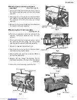
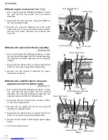
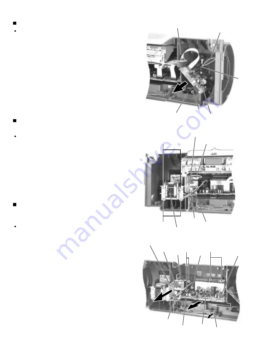
Prior to performing the following procedure, remove
the right and left side grilles, the front cabinet assembly,
the cassette mechanism assembly and the cassette
chassis.
Disconnect the harness from connector CN192 and
CN193 on the power supply board respectively.
Remove the four screws F attaching the power
transformer assembly.
1.
2.
Remove the power transformer assembly
(See Fig.10)
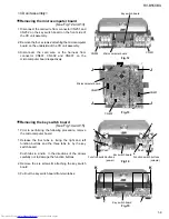
Prior to performing the following procedure, remove
the right and left side grilles, the front cabinet
assembly, the cassette mechanism assembly, the
cassette chassis and the CD unit assembly.
Disconnect the 5pin harness from connector CN191
on the power supply board.
Remove the two screws G and the one screw H
attaching the amplifier board.
Disconnect the harness from connector CN192 and
CN193 on the power supply board respectively.
Remove the two screws I attaching the power supply
board.
Pull out the battery board.
1.
2.
3.
4.
5.
Remove the amplifier board, the power
supply board and the battery board
(See Fig.11)
Prior to performing the following procedure, remove
the right and left side grilles, the front cabinet
assembly.
Disconnect the card wire from connector CN403 on
the microcomputer board.
Remove the screw E attaching the tuner board
holder and pull out the tuner board holder together
with the tuner board. Disconnect the antenna wire
from TP1.
1.
2.
Removing the tuner board (See Fig.9)
Fig.11
Microcomputer board
CN403
TP1
Antenna wire
Tuner board
Tuner board holder
E
F
F
CN193
CN191
CN192
Power transformer assembly
Power supply board
G
H
I
CN631
CN631
Battery board
CN193
CN192
Power supply board
Amplifier board
CN191
Fig.10
Fig.9

