RS-WP1WT
1-6
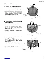
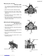
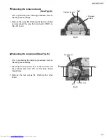
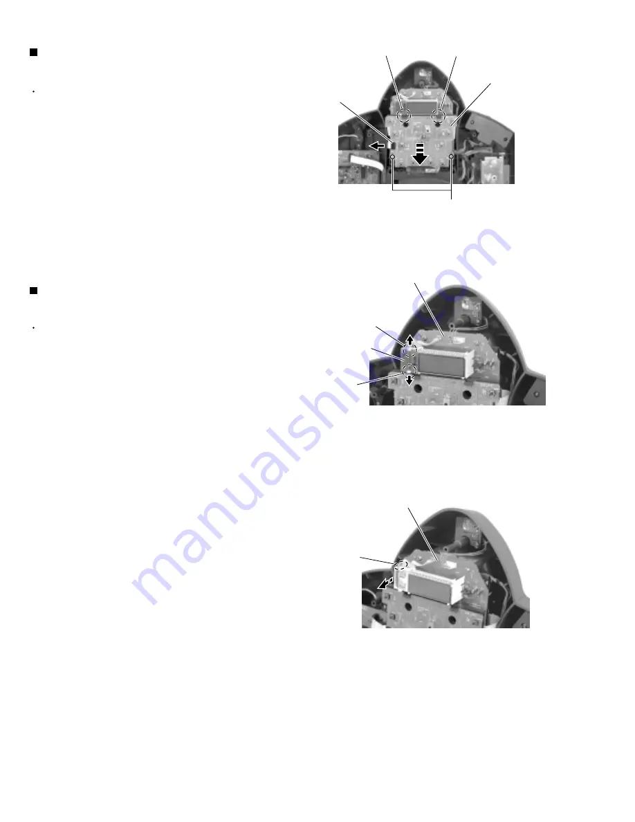
Prior to performing the following procedures, remove
the rear panel assembly.
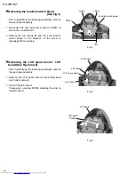
Disconnect the card wire from connector CN921 on
the function switch board.
Remove the two screws
D
and move the function
switch board in the direction of the arrow to
disengage the two joints
a
.
1.
2.
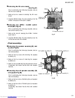
Removing the function switch board
(See Fig.4)
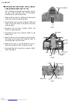
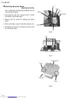
Prior to performing the following procedures, remove
the rear panel assembly.
Remove the LCD spare board while pulling each
joint hook
b
outward.
Pull out the LED board.
If necessary, unsolder FW925 soldering the wire on
the LED board.
1.
2.
Removing the LCD spare board / LED
board (See Fig.5 and 6)
Fig.5
Fig.6
Fig.4
D
Joint a
Joint a
Function switch board
CN921
LCD board
Joint hook b
Joint hook b
LCD board
LCD spare board
LED board
FW925
Содержание RS-WP1WT
Страница 37: ...RS WP1WT 3 2 M E M O ...
Страница 57: ...RS WP1WT 2 4 ...
Страница 66: ...RS WP1WT 2 13 Tuner Board Block No 04 ...
Страница 68: ...RS WP1WT 2 15 ...

