RS-WP1WT
1-29
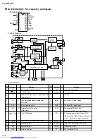
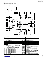
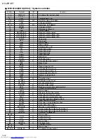
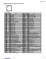
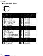
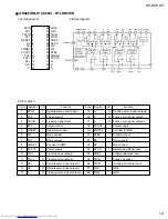
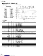
MN35530 (IC601) : Digital servo & processor
1. Terminal layout
2. Pin function
21
40
80
61
20
1
~
~
~
~
41
60
Pin
No.
Symbol
1
2
3
4
5
6
7
8
9
10
11
12
13
14
15
16
17
18
19
20
21
22
23
24
25
26
27
28
29
30
31
32
33
34
35
36
37
38
39
40
-
I
I
I/O
I/O
I
I
I/O
I/O
O
O
O
O
O
O
O
O
O
O
-
-
O
O
O
O
O
O
O
O
O
I
I
I
I
I
I
I
I
I
I
DVD3V
D0
D1
NWE
NRAS
D2
D3
NCAS0
NCAS1
A8
A7
A6
A5
A4
A9
A0
A1
A2
A3
DVSS2
DVDD2
SPOUT
TRVF
TRVR
TRF
TRR
FOF
FOR
FBAL
TBAL
CSEL
FE
TE
RF ENV
OFT
NRFDET
BDD
LDON
ARF
IREF
Power supply
Data input
Data input
Write enable
Low address strove
Data input
Data input
Column address strove 0
Column address strove 1
Adress output
Adress output
Adress output
Adress output
Adress output
Adress output
Adress output
Adress output
Adress output
Adress output
Connect to GND
Power supply
Spindle control output
Traverse control output (F)
Traverse control output (R)
Tracking control output (F)
Tracking control output (R)
Focus control output (F)
Focus control output (R)
Focus balance adjust output
Trarcking balance adjust output
Chip select input
Focus error signal input (Analog input)
Tracking error signal input (Analog input)
RF envelope signal input (Analog input)
Off track signal input (H:off track)
RF signal input
BDO input pin (L:detect)
Laser ON signal output (H:on)
RF signal input
Reference current input
I/O
Function
Pin
No.
Symbol
41
42
43
44
45
46
47
48
49
50
51
52
53
54
55
56
57
58
59
60
61
62
63
64
65
66
67
68
69
70
71
72
73
74
75
76
77
78
79
80
I
I/O
I
I/O
I
-
-
O
-
O
-
I
-
-
O
-
-
-
-
O
I
I
I
O
O
O
O
I
I
I
-
I
-
I
-
-
I
O
-
-
ADPVCC
DSLF
DRF
PLLF
VCOF
AVDD2
AVSS2
OUTL
AVSS2
OUTR
AVDD1
FSEL
TMOD1
TMOD2
FLAG
CVS
EXTO
EXT1
EXT2
TX
MCLK
MDATA
MLD
BLKCK
SQCK
SUBQ
DMUTE
STAT
NRST
PC
PMCK
SMCK
SUBC
SUCK
NCLDCK
NTEST
X1
X2
DVDD1
DVSS1
Vcc for A/D input
Loop filter pin for DSL
Bias pin for DSL input
Loop filter pin for DSL
Vcc OFF input
Power supply
Connect to GND
Lch audio output
Connect to GND
Rch audio output
Power supply
FS selection input
Connect to GND
Connect to GND
Flag output signal
Non connect
NC
NC
NC
Digtal audio interface output
Micon command clock signal input
Micon command data input
Micon command load signal input
Sub-code block clock signal output
Outside clock for sub-code Q resistor input
Sub-code Q-code output
Digtal mute
Stetus signal input
Reset input
Power control input
Non connect
Serial Master clock input
Non connect
Clock input for sub code/serial output
NC
NC
Input of 33.8688MHz x'tal oscillation circuit
Out of x'tal oscillation circuit
Power supply
Connect to GND
I/O
Function
Содержание RS-WP1WT
Страница 37: ...RS WP1WT 3 2 M E M O ...
Страница 57: ...RS WP1WT 2 4 ...
Страница 66: ...RS WP1WT 2 13 Tuner Board Block No 04 ...
Страница 68: ...RS WP1WT 2 15 ...

