background image

5

6

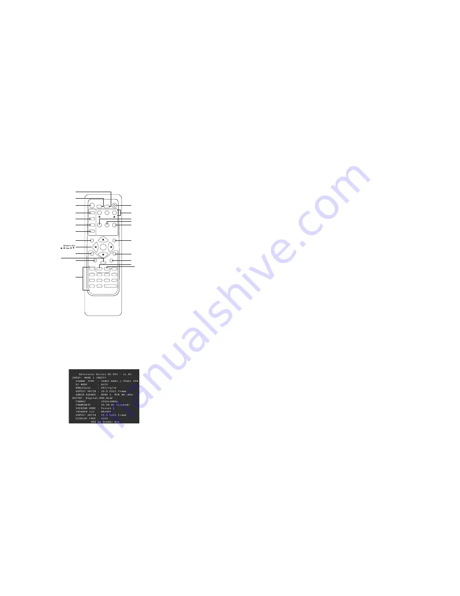
INPUT SELECT

STANDBY

POWER

INPUT

ADJUST

CONFIG

PICTURE

CONTROL

OUTPUT

SETUP

MENU

EXIT

16:9

4:3

AUTO

VIDEO 1

S-VIDEO 1

COMP 1

HDMI 2

VIDEO 2

S-VIDEO 2

COMP 2

HDMI 3

ENTER

HDMI 4

BORDER

CROP

INFO

CURTAIN

MEMORIES

RGBHV

HDMI 1

SDI

ASPECT

ZOOM

PAN

ON/OFF

DISPLAY

PROFILES

VIEWING

MODES

INPUT

ASPECT

RATIO

TEST PATTERN

ENTER

Standby

Info

Curtain

Output Setup

Configuration

Picture Control

Input Adjust

Menu

Border

Zoom

Input Select

(HDMI 1, HDMI 2, HDMI 3, HDMI 4,

Component 1, Component 2,

RGBHV/Component,

S-Video 1, S-Video 2,

Video 1, Video 2, AUTO)

Aspect

Exit

Crop

Pan

Power

Input Aspect

Ratio

Viewing Modes

Display Profiles

4:3

16:9

Test Patterns

(Left, On/Off, Right)

 5

26

17

*

32

4

20

21

21

6

5

5

28

26

25

22

4

4

20

18

20

18

21

Remote Control Overview

For additional information about the functions of these buttons, turn to the pages listed below.

An asterisk (*) indicates a feature that has not yet been implemented.

Power/Standby Buttons
The rs-Vp2 remote has a Power and a Standby button. The Power button always turns the rs-Vp2 
on and the Standby button always put the unit into Standby mode. 

Info Button
This rs-Vp2 has an ‘info’ screen which brings up a window on the connected display which contains 
important  input  and  output  information  which  can  help  with  troubleshooting.  The  software  version 
which is loaded in the unit will also be displayed on this window and on the front panel display of the 
RS-VP2.

Curtain Button
The rs-Vp2 remote has a Curtain button which allows you to close a ‘curtain’ over the image. This 
feature is especially useful when an image is paused on a display susceptible to burn-in or a transition 
while switching inputs as part of a macro on a universal remote or automation system.

Discrete IR Codes and Serial Automation Protocol

almost all commands that are available in the on screen display can be executed discretely using a 
programmable  IR  remote  control  or  automation  system  connected  via  an  RS232  serial  connection. 
These codes are available at www.jvc.com/pro

Non-Volatile Memory Settings

The  RS-VP2  stores  a  variety  of  user  settings  in  non-volatile  memory.  Non-volatile  memory  
retains its contents when power is lost. There is one group of system settings and one group of user 
settings.

Installation Guidelines

Take special care with the RS-VP2 installation to ensure optimal performance. Pay particular attention to 
the bulleted items that begin below and to other precautions that appear throughout this guide.


Do . . . 

• 

Install the RS-VP2 on a solid, flat, level surface such as a table or shelf.  


You can also install the RS-VP2 in a standard 19” equipment rack using an optional  


rack-mount kit available from authorized JVC resellers or directly from JVC.

• 

Select a dry, well-ventilated location.

• 

Use only the included external power supply.

• 

Avoid excessive humidity, sudden temperature changes or temperature extremes.

• 

Use only accessories recommended by the manufacturer to avoid fire, shock or other hazards.

• 

Unplug your RS-VP2 before cleaning. Use a damp cloth for cleaning.

Don’t . . . 

• 

Install the RS-VP2 on an unstable surface or one that is unable to support all    


four of its feet, unless it is installed in an equipment rack.

• 

Stack the RS-VP2 directly above heat-producing equipment such as power  


amplifiers or other components that generate heat during use.

• 

Expose the RS-VP2 to a high temperatures, humidity, steam, smoke, dampness,  


or excessive dust. Avoid installing the RS-VP2 near radiators and other heat  


producing appliances.

• 

Install the RS-VP2 near unshielded TV or FM antennas, cable TV decoders, and   


other RF -emitting devices that might cause interference.

• 

Place the RS-VP2 on a thick rug or carpet or cover the RS-VP2 with cloth.  


This might prevent proper cooling.

• 

Attempt to service this unit. Instead, disconnect it and contact your Authorized JVC  


Reseller or contact JVC directly.

• 

Open or remove unit panels or make any adjustments not described in this manual.  


Attempting to do so could expose you to dangerous electrical shock or other hazards.    


It may also cause damage to your RS-VP2.

• 

Obstruct the front panel IR receiver window shown in “Remote Control Overview”.

• 

Do not attempt to use the remote control out of line of sight with the IR receiver.  


Doing so will cause improper operation.

Содержание RS-VP2

Страница 1: ......

Страница 2: ...Outputs 8 Audio Inputs 8 Audio Outputs 9 12V Trigger Outputs 9 RS232 Serial Connection 9 Power Supply Input 9 S e ct i o n 3 S e t u p 10 Initial Setup 10 STEP 1 Power Up 10 STEP 2 Connect the RS VP2 to the Display 10 STEP 3 Selecting the Optimal Output Resolution on the RS VP2 for the Connected Display 10 STEP 4 Connecting the Sources to the RS VP2 12 STEP 5 Configuring the Sources to Get Maximum...

Страница 3: ...24 Auto Input Priority Selection 25 Audio Input 25 AV Lip Sync 25 Picture Controls 25 Fine Detail Enhancement 25 Edge Enhancement 25 Brightness 25 Contrast 26 Saturation 26 Hue 26 Y C Delay 26 Chroma Filter Auto CUE C 26 Configuration 26 Test Patterns 26 Auto Standby 26 LED Brightness 27 User Mode 27 On Screen Display Control OSD 27 Serial Port Rate 27 Factory Default 27 Software Update 27 12V Tri...

Страница 4: ...the total It can also show you how to properly connect it and use it with the other components in your system Unpacking and Inspection Please verify that your RS VP2 carton contains the following items RS VP2 Video Processor Universal 6V 7A AC to DC Power Converter US IEC Power Cord International Customers consult your local authorized JVC reseller Remote Control RS VP2 Owner s Manual RS VP2 Quick...

Страница 5: ...if you are looking at the front panel display FPD you will see Picture Control on the top line and Contrast on the bottom line This is abbreviated as Picture Control Contrast Next press u to adjust the setting and then press p until the value is 5 Finally press Exit Text that is in bold refers to a button on the remote control of front panel of the RS VP2 Text that is in quotes references an item ...

Страница 6: ...ile Memory Settings The RS VP2 stores a variety of user settings in non volatile memory Non volatile memory retains its contents when power is lost There is one group of system settings and one group of user settings Installation Guidelines Take special care with the RS VP2 installation to ensure optimal performance Pay particular attention to the bulleted items that begin below and to other preca...

Страница 7: ...A 60 Colorspace RGBHV and YPbPr HDMI 1 HDMI 2 HDMI 3 and HDMI 4 Formats 480i p 60 576i p 50 720p 50 60 1080i 50 60 1080p 24 25 30 50 60 VGA 60 SVGA 60 XGA 60 SXGA 60 Colorspace RGB YCbCr 4 4 4 YCbCr 4 2 2 Bit Depth 8 10 bit processed Up to 12 bit passthrough Optional Precision HD SDI Dual Input Module Formats 480i 60 576i 50 720p 60 1080i 50 60 1080p 24 25 30 Colorspace YCbCr 4 2 2 Bit Depth 8 10 ...

Страница 8: ...ns and verify that the power outlet does supply power with another device IMPORTANT Use only the power supply that came with your RS VP2 or a replacement procured directly from JVC STEP 2 Connect the RS VP2 to the Display Displays with a DVI or HDMI Input Based on the factory default settings just connecting an RS VP2 to a display with an HDMI or DVI input should complete this step as the default ...

Страница 9: ... test pattern is displayed incorrectly the resulting image does not look like a fine checker board and may have irregular patterns When this is the case the chosen output resolution may not be the native resolution of the display or the display may scale all input signals even if the input reso lution is already at native resolution Check to make sure that the output resolution selected on the RS ...

Страница 10: ...re the BD player to output 1080p 24 if the player allows if not use 1080i 60 and the Forced 3 2 mode See Step 6 Blu ray Player Configure the BD player to output 1080p 24 if the player allows if not use 1080i 60 and the Forced 3 2 mode See Step 6 Game Consoles Xbox Configure the Xbox to output all resolutions 480i 480p 720p and 1080i Xbox360 360Elite Configure the Xbox360 to output 720p PS2 Configu...

Страница 11: ...level When the brightness and contrast are adjusted correctly you should be able to see the 1 IRE and 2 IRE above black bars on the black background and the 1 IRE and 2 IRE below white bars should be visible on the white background When the brightness is adjusted correctly black objects should appear black with the details still intact and lighter areas should be light not gray with the details st...

Страница 12: ...d forth at the chosen output frequency selected in the framerate parameter When this test pattern is displayed correctly the bar moves smoothly across the screen and bounces from side to side When this pattern is displayed incorrectly this bar may tear as it moves across the screen If your display does accept 24Hz or 48Hz a Display Profile should be saved for viewing film based content in addition...

Страница 13: ...OSD select the control that you would like to adjust Horizontal or Vertical zoom and push the Enter button to show the current Zoom setting Push the p and button to increase or decrease the zooming factor Zoom can only increase the size of the image NOTE The Zoom and Pan functions are applied to the input signal not the output This is an important consideration especially for the Pan function For ...

Страница 14: ...have not customized the aspect ratio and the current aspect ratio settings are the same as a system defined preset In this case the system will not allow you to save the preset setting Input Adjust Control Push the Input Adjust button once to show the current input adjustment function You can cycle through the available functions by pushing this button repeatedly Mosquito Noise Reduction The RS VP...

Страница 15: ...lt overscan value is 0 which means 100 of the input image is shown The maximum overscan value is 20 which means the input image is scaled up by 120 This is a setting that is saved on a per input per format basis To adjust the overscan level 1 Push the p or q button The current level is shown 2 Push the p or q button to decrease or increase the amount of overscan 3 The Overscan value is applied to ...

Страница 16: ...usts the ratio between white and black signal levels and is effective as a gain control The difference between this and the Brightness control is that this adjusts the difference between the brightest and darkest part of the image Note that all displays have a maximum white level Going beyond this level only clips the upper gray levels and you will lose color resolution at the brighter levels Adju...

Страница 17: ...ton The FPD displays No 2 Press the same button to switch to Yes 3 Confirm this selection by pressing the Enter button NOTE Resetting the RS VP2 to the factory defaults will cause all previously saved settings to be lost Record any important settings before performing this action Software Update Use this parameter to install the latest software into your RS VP2 The latest software is available at ...

Страница 18: ...e Display aspect ratio The example below shows 16 9 projector 1 78 1 and a 2 35 1 screen you can shift the image to match the exact location of your screen In this situation the image is shifted down putting all of the mask at the top of the projected image Underscan represents the visible display area a sub set of the Active Output Area Underscan is like a negative zoom which preserves the aspect...

Страница 19: ...ve if the back and forth panning motion of the test pattern is smooth or if it jerks or stutters If the former then the display supports that particular resolution and frame rate without perform ing any frame rate conversion of its own if the latter then the display is performing frame rate conversion on the signal Examples These configuration options provide a lot of flexibility to deal with diff...

Страница 20: ...o ensure that damage is not caused please check the manual of the device that you intend on connecting to the RS VP2 before inserting the trigger plug into the jack Trigger 1 is powered on when the RS VP2 is powered on Trigger 1 is powered off when the RS VP2 is put into Standby mode This can be useful for powering on a display or motor izing a screen or lift Trigger 2 can be programmed to be powe...

Страница 21: ...ertical Range 0 200 Presets 4 3 Full Frame Letterbox 16 9 Full Frame 4 3 Stretch Preset 1 Preset 2 Preset 3 Preset 4 Preset 5 Preset 6 Preset 7 Preset 8 Preset 9 Preset 10 User Save User to Preset 1 No Yes Preset 2 No Yes Preset 3 No Yes Preset 4 No Yes Preset 5 No Yes Preset 6 No Yes Preset 7 No Yes Preset 8 No Yes Preset 9 No Yes Preset 10 No Yes Input Adjust Mosquito Noise Reduction Off Low Med...

Страница 22: ...try Brightness Contrast Checkerboard Vertical Lines Horizontal Lines Judder Color8 Bars75 Color8 Bars100 Window IRE10 Window IRE20 Window IRE30 Window IRE40 Window IRE50 Window IRE60 Window IRE70 Window IRE80 Window IRE90 Window IRE100 Gray Ramp Xhatch Coarse Xhatch Fine Focus Half B W H Clr7 Bars75 H Clr7 Bars100 H Clr8 Bars75 H Clr8 Bars100 Black White Red Green Blue Cyan Magenta Yelllow Auto St...

Страница 23: ... Front Porch Range Vertical Sync Range Vertical Back Porch Range Aspect Ratio Display 4 3 5 4 16 9 Custom Lens Mode 1 Mode 1 Auto Mode 2 None Screen 4 3 16 9 2 35 1 Custom Range 1 00 3 00 Image Shift Vertical Range 30 30 Horizontal Range 30 30 Underscan Range 0 100 Sync Type Bi Level Tri Level Composite H V H V H V H V Color Space RGB YPbPr YCbCr 4 2 2 YCbCr 4 4 4 Output Level Video PC Framerate 2...

Страница 24: ...r 2 Lens On Off Audio Select S PDIF HDMI Display Profile Select Profile 1 Profile 2 Profile 3 Profile 4 Profile 5 Profile 6 Profile 7 Profile 8 Profile 9 Profile 10 Save Profile 1 No Yes Profile 2 No Yes Profile 3 No Yes Profile 4 No Yes Profile 5 No Yes Profile 6 No Yes Profile 7 No Yes Profile 8 No Yes Profile 9 No Yes Profile 10 No Yes Auto Off On ...

Страница 25: ...erate conversion 30 front panel display FPD 7 G game console 13 19 H HDCP mode 20 33 hue 26 I image mapping 16 info screen 5 input adjustment controls 22 input aspect ratio control 18 input format settings 31 installation guidelines 6 L line offset function 20 M menu navigation 4 N non volatile memory 31 O output aspect ratio control 29 output setup 28 overscan function 23 P package contents 2 pan...

Страница 26: ......

Страница 27: ......

Отзывы: