background image

Name of Parts

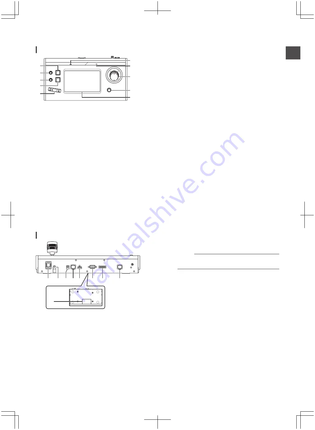
Front panel

.

A
B
C

D
E

F

G

H

I
J

A

USER1 button

For switching the settings menu.

B

F1 knob

Used for the multi-function settings.

C

F2 knob

Used for the multi-function settings.

D

USER2 button

For switching the settings menu.

E

Zoom lever

For performing the zoom operation of the remote camera.

F

ALARM lamp

Red

: Lights up when the alarm is activated.

G

POWER lamp

Green : Lights up while the power is on.

H

Control lever (F3)

0

For operating pan/tilt of the remote camera.

0

Used for the multi-function settings.

I

Focus knob/Push auto button

0

For performing the focus operation of the remote camera.

0

Used for the one-push auto focus function.

J

Operation panel

Used as a touch panel.

Rear panel

.

A B C D E

F G

I

H

A

Power switch

For turning the power on or off.

B

Cable clamp

For preventing the AC adapter cable from falling out.

C

DC 12V terminal

For connecting the supplied AC adapter.

D

LAN terminal

For connecting a LAN cable.

E

SERVICE terminal

For use during servicing.

F

TALLY terminal

Used for TALLY connection.

G

SETTING switch

1 to 4

: For switching TALLY IN and OUT.

5 to 8

: Used for servicing only.

H

SERIAL terminal

Not used.

I

Rating label

Basic Operations

For details, refer to the instruction manual.

1

Turn on the power.

0

Set the power switch at the rear of this unit to “On”. The

LED lamp lights up in green.

2

Configure the settings of this unit.

0

Set the IP address of this unit as follows.

A

Select [SETTINGS] on the top screen of the control

panel.

0

If the top screen doesn’t appear, select [HOME].

B

Select [Network].

C

Select [CONTROLLER].

0

The IP address setting screen appears.

D

Enter the IP address and press [ENTER].

3

Configure the camera setting.

0

Set the camera to be operated as follows.

A

Select [SETTINGS] on the top screen of the control

panel.

0

If the top screen doesn’t appear, select [HOME].

B

Select [Network].

C

Select [CAMERA REGISTRATION].

D

Select [AUTO] to register the camera.

Memo : 

0

For details on the [MANUAL] settings, please refer

to the “INSTRUCTIONS” on the website.

0

To change the camera to be operated, perform the above

operations again.

Name of Parts

9

Gettin

g Started

Содержание RM-LP100E

Страница 1: ... U for USA and Canada E for Europe Only U models RM LP100U have been evaluated by UL Please read the following before getting started B5A 1723 00 RM LP100U RM LP100E Details INSTRUCTIONS BASIC REMOTE CAMERA CONTROLLER Specifications and appearance of this unit are subject to change for further improvement without prior notice For details on settings and operation refer to INSTRUCTIONS on the websi...

Страница 2: ...ÉE DANS CE DOCUMENT RISQUE D ENTRAÎNER UNE EXPOSITION DANGEREUSE AUX RAYONNEMENTS L UTILISATEUR NE DOIT PAS OUVRIR NI RÉPARER L APPAREIL DE LUI MÊME FAIRE APPEL À UN PERSONNEL QUALIFIÉ POUR L ENTRETIEN AVIS RISQUE DE CHOC ELECTRIQUE NE PAS OUVRIR CAUTION RISK OF ELECTRIC SHOCK DO NOT OPEN WARNING TO PREVENT FIRE OR SHOCK HAZARD DO NOT EXPOSE THIS UNIT TO RAIN OR MOISTURE CAUTION This unit should b...

Страница 3: ...liquids such as cosmetics or medicines flower vases potted plants cups etc on top of this unit 7 DO NOTplace any naked flame sources such as lighted candles on the apparatus 8 AVOID violent shocks to the unit during transport When the equipment is installed in a cabinet or a shelf make sure that it has sufficient space on all sides to allow for ventilation 10cm or more on both sides on top and at ...

Страница 4: ...pe may vary Replace an exhausted battery with a new one promptly If you will not use the remote control for a long time remove the batteries If leaked battery fluid gets on your skin or clothing rinse immediately and thoroughly If it gets into you eye bathe your eye well rather than rubbing and seek medical treatment immediately Leaked battery fluid that gets into your eye or your clothing may cau...

Страница 5: ... shall be connected to a MAINS socket outlet with protective earthing connection Main Plug The Main Plug is used as the disconnect device the disconnect device shall remain readily operable Even if the display window of the unit is unlit the main power supply is not cut off unless the power cord is unplugged The main power supply for this unit is controlled by inserting or removing the power plug ...

Страница 6: ...panels or doors on equipment DON T continue to operate the equipment if you are in any doubt about it working normally or if it is damaged in any way switch off withdraw the mains plug and consult your dealer DON T remove any fixed cover as this may expose dangerous voltages DON T leave equipment switched on when it is unattended unless it is specifically stated that it is designed for unattended ...

Страница 7: ... 㞈埩䢻ḇᶮ ḻ㮒 䘅㱖 奅 䘅䌰 ἀ䒩㚠旑ɝ 夂䒩ㆸ ἀ䒩㚭Ḩ 㕷忶 㱩ゐḌ柺ᶮ䘅 柺奅 澔ṏ 御㕦㚠 㫥 㞈㞈ⅻ䘅㚠旑ᶻ㫣澐䌰 ἀ䒩㚠旑澑㕣 ᶎẛ㯢㝔䌰 ᶎẛḨ䒠 ḻỔ㚊 䘅䇪岩ɝ 旅ṷ 㴉侘 晷ṷ䘅䌰 ἀ䒩㚠旑 ᶌ 䢻澢 澐ᶎ Ḩ ᶮ 䘅旅ṷ 㴉侘 晷ṷ ᶎ䙹 ɝ澑 忦 ɜḥ㳂廭 ɜ䒶亇䯼澢21ⷵ 㚭埩㞽 TK0U22475 䘅奅 亗 ɝ ȵ澢埩䢻学㚊 䇪岩 学恩ṷ 㚊 岩㛑㔚ᶮ䘅 慐 HC0U37683 奅 䘅旑慐夂㯃Ṧᶌɝ 澢埩䢻学㚊 䇪岩兴 学恩ṷ䘅㝑ᶁ 岩㛑㔚ᶮ䘅 慐崆ⅻ HC0U37683奅 䘅旑慐夂㯃ɝ For RM LP100E GB4943 1 2011 GB9254 2008 GB17625 1 2012 Safety Precautions 7 Getting Started ...

Страница 8: ...ndensation is not allowed 0 Near equipment that emits strong magnetic fields such as transformers or motors 0 Near equipment that emits radio waves such as transceivers and mobile phones 0 Locations with excessive dust and sand 0 Locations prone to moisture such as window side 0 Locations that are subjected to radiation X rays salt attack or corrosive gases 0 Places subject to smoke or vapor such ...

Страница 9: ...ICE terminal For use during servicing F TALLY terminal Used for TALLY connection G SETTING switch 1 to 4 For switching TALLY IN and OUT 5 to 8 Used for servicing only H SERIAL terminal Not used I Rating label Basic Operations For details refer to the instruction manual 1 Turn on the power 0 Set the power switch at the rear of this unit to On The LED lamp lights up in green 2 Configure the settings...

Страница 10: ...er switch at the back of the unit and power on again If it still does not start up stop using the unit disconnect the power cord from the power outlet and consult a dealer or our service center Connection Diagram RM LP100 KY PZ100 KY PZ100 KY PZ100 LAN cable HUB Up to 100 cameras can be connected concurrently 10 Troubleshooting Others ...

Страница 11: ...LY terminal D sub 9 pin LAN terminal 10BASE T 100BASE TX DC terminal DC jack for the supplied AC adapter Accessories Accessories Warranty Card U model only 1 INSTRUCTIONS BASIC 1 AC Adapter 1 Power Cord U model 1 E model 2 Wire Clamp 1 Screw M3 1 Dimensional Outline Drawing Unit mm 350 182 110 62 177 The specifications and appearance of this product are subject to changes for further improvement w...

Страница 12: ...RM LP100U RM LP100E REMOTE CAMERA CONTROLLER 2016 JVC KENWOOD Corporation B5A 1723 00 ...

Отзывы: