


10
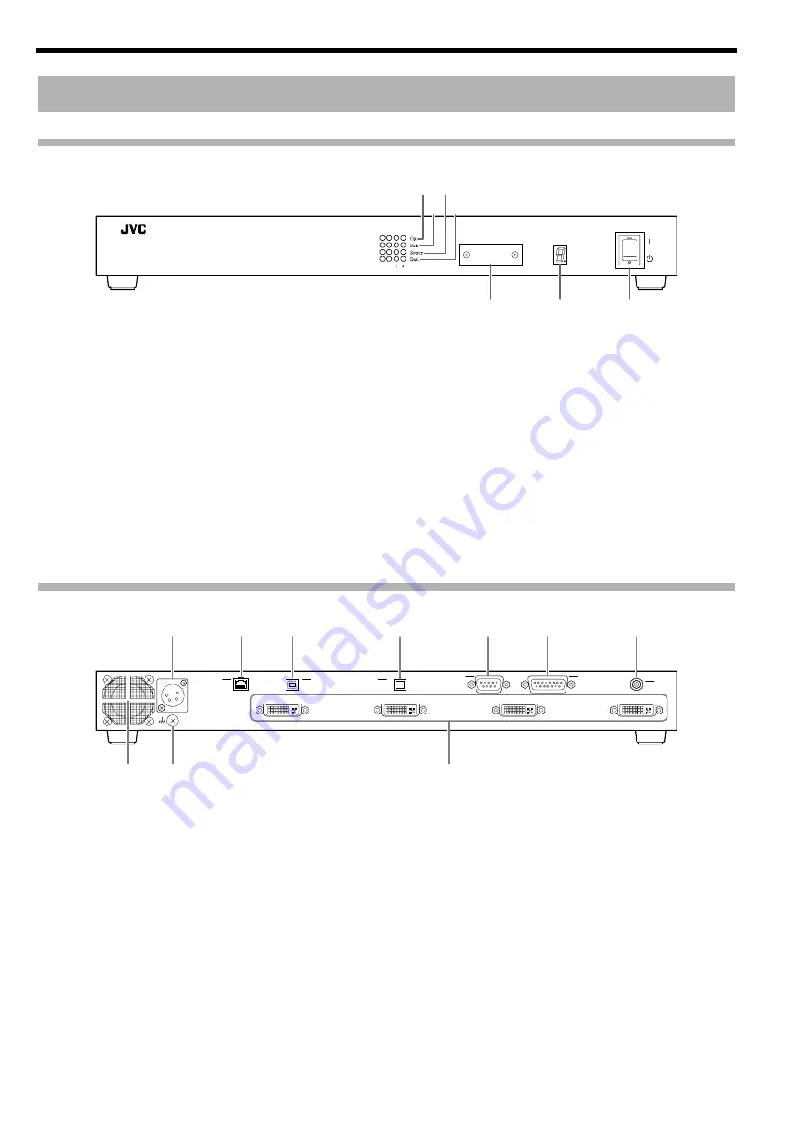
Front
A
[Opt] Indicator
Lights up when an optical fiber cable is connected between
the optical transmitter and optical receiver units, and appears
blinking if cable is not connected.
B
[Sink] Indicator
Lights up when a monitor display is connected. (Monitors
HPD)
C
[Source] Indicator
Lights up when a video signal generator is connected.
(Mo5 V supply)
D
[Dual] Indicator
Lights up when there is a dual-link signal input.
E
MODE
Do not open.
Changing the settings will cause malfunction.
F
STATUS Indicator
This unit performs initialization when the power is turned on.
The initialization takes about 15 seconds.
The STATUS indicator shows the progress of the initialization
with a dotted number.
If the indicator shows "0." to "8." in order and finally "1"
(factory default unit ID), the unit is in working condition.
G
POWER Switch
Use this to turn on/off the main power supply of this unit.
Rear
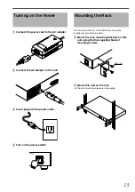
H
Power Input Terminal
Connect the supplied AC adapter to this terminal.
I
LAN Terminal (RJ-45)
This unit can be controlled by connecting it to a computer
using a LAN cable.
J
USB Terminal (Type B)
This unit can be controlled by connecting it to a computer
using a USB cable.
K
Optical Input Terminal (MPO 12-fiber)
For connecting a 12-fiber MPO connector cable.
L
REMOTE Terminal (D-sub 9 pins)
This unit can be controlled by connecting it to a computer
using a RS-232C cross cable.
M
EXT. CONTROL Terminal (D-sub 15 pins)
This is an extension terminal.
N
SYNC IN Terminal (BNC)
Input terminal for sync signals.
O
Cooling Fan
P
Earth Terminal
Connect the earth wire to this terminal.
Q
DVI OUT to 4 Terminals (DVI-D)
Output terminal for video signals. Connect it to the projector
using a DVI cable.
Names and Functions of Parts
%
&
MODE
STATUS
GRAPHICS INTERFACE
Visualization Series
F
E
A C
B D
G
DC IN 12V
DVI 4 OUT
REMOTE
EXT. CONTROL
DVI 3 OUT
DVI 2 OUT
DVI 1 OUT
SYNC
IN
USB
OPT
LAN
H
I
J
O
P
Q
K
L
M
N
CAUTION
: Do not block the cooling fan with papers, cloth or
soft cushions. Doing so may cause heat to trap
inside the unit and result in fire or malfunction.
Содержание PK-VS4GD3
Страница 28: ......
Страница 29: ...GRAPHICS INTERFACE PK VS4GD3 取扱説明書 MODE STATUS GRAPHICS INTERFACE Visualization Series ...
Страница 51: ......
Страница 52: ...PK VS4GD3G GRAPHICS INTERFACE PK VS4GD3 Printed in Japan 1304TTH SW X 2013 JVCKENWOOD Corporation ...


