


3-5
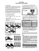
3.4 AUDIO CIRCUIT
Notes:
• This adjustment should be done after the “REC color
(colour) level adjustment” for the video circuit has
been completed.
• GND (Ground) should be taken from the Tuner shield
case.
Signal
(A1)
• Ext. input
(A2)
• Audio: No signal
(A3)
• Video: Color (colour) bar signal [PAL]
Mode
(B)
• S-VHS LP
Equipment
(C)
• Oscilloscope
Measuring point
(D)
• TP2253 (A. PB. FM)
External trigger
(E)
• TP111 (D.FF)
EVR mode
(F1)
• Jig RCU: Code “57”
EVR address
(F2)
• A: 30 (Press remote controller “3” and
“0” keys.)
Specified value
(G1)
• 450 ±100 mVp-p
(G2)
• More than 300 mVp-p
Adjustment tool
(H)
• Jig RCU [PTU94023B]
• Digit-key remote controller
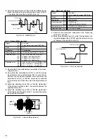
(1) Apply the external trigger signal to D.FF (E) to observe
the Audio PB FM waveform at the measuring point (D).
(2) Record the signal (A3) with no audio signal input in the
mode (B), and play back the recorded signal.
(3) Press the channel buttons (+, –) simultaneously to enter
the manual tracking mode. This also brings tracking to
the center (centre).
(4) If the A.PB FM level is not within the specified value (G1),
perform the adjustment in a following procedure.
(5) Set the VCR to the EVR mode by transmitting the code
(F1) from the Jig RCU.
(6) Set the EVR address to (F2) by pressing the button of
the digit-key remote controller.
(7) Adjust with the channel buttons (+, –) on the VCR (or on
the remote controller) so that the A.PB FM level of the
higher channel level becomes the specified value (G1).
(Adjust before recording, then confirm it by playing back.)
(8) If the specified value (G1) is not obtained, adjust with the
channel buttons (+, –) so that the waveform level of the
lower channel level becomes the specified value (G2).
(Adjust before recording, then confirm it by playing back.)
(9) Release the EVR mode of the VCR by transmitting the
code (F1) from the Jig RCU again. (When the EVR mode
is released, the adjusted data is memorized.)
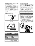
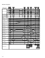
3.4.1 Audio REC FM
Fig. 3-4-1a Audio REC FM
V. rate
Specified
value (G1)
Specified
value (G2)
3.5 PAL/SECAM CONVERTER CIRCUIT
Note:
• Unless otherwise specified in this P/S Converter cir-
cuit adjustments, all measuring points and adjustment
parts are located on the P/S Converter board.
3.5.1 fH VCO
Fig. 3-5-1a fH VCO
FH–SYNC
Specified value (G)
H.rate
(1) Connect the short wire between the short point (D2) and
the GND (Ground).
(2) Observe the waveform appeared at the measuring point
(D1).
(3) Adjust the adjustment part (F) so that the fH SYNC fre-
quency becomes the specified value (G).
(4) Disconnect the short wire between the short point (D2)
and the GND (Ground).
Signal
(A1)
• Ext. input
(A2)
• Color (colour) bar signal [SECAM]
Mode
(B)
• EE
Equipment
(C)
• Oscilloscope
Measuring point (D1)
• IC3504 pin 4 (H OUT)
Short point
(D2)
• TP3503
Adjustment part
(F)
• VR3501 (FH FREE RUN ADJ.)
Specified value
(G)
• fH = 15.625 ± 0.2 kHz
(T = 64 ± 0.8 µsec)
3.5.2 DEMOD Fo
(1) Observe the B-Y waveform at the measuring point (D1).
(2) Adjust the adjustment part (F1) so that the difference be-
tween the blanking level and the pedestal level of the B-
Y waveform becomes the specified value (G).
Signal
(A1)
• Ext. input
(A2)
• Color (colour) bar signal [SECAM]
Mode
(B)
• EE
Equipment
(C)
• Oscilloscope
Measuring point (D1)
• TP3501 round (B-Y)
(D2)
• TP3502 round (R-Y)
Adjustment part
(F1)
• L3513 (SECAM DECODE ADJ.)
(F2)
• VR3502 (SECAM DECODE ADJ.)
Specified value
(G)
• Less than 20 mVp-p
Fig. 3-5-2a DEMOD Fo-1
Pedestal level
Specified value (G)
B – Y signal
Blanking level
H.rate
(3) Observe the R-Y waveform at the measuring point (D2).
Содержание HR-S6700MS
Страница 5: ......


