


3-3
Signal
(A1)
• Ext. input
(A2)
• Color (colour) bar signal [PAL]
Mode
(B)
• EE
Equipment
(C)
• Oscilloscope
Measuring point (D)
• Y OUT terminal (75
Ø
terminated)
EVR mode
(F1)
• Jig RCU: Code “57”
EVR address
(F2)
• A:11 (Press remote controller “1” key twice)
Specified value
(G)
[HR-S6700MS]
• 1.00 ±0.05 Vp-p
[HR-S7700MS]
• 1.00 ±0.03 Vp-p
Adjustment tool
(H)
• Jig RCU [PTU94023B]
• Digit-key remote controller
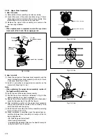
(1) Observe the Y OUT waveform at the measuring point (D).
(2) Set the VCR to the EVR mode by transmitting the code
(F1) from the Jig RCU.
(3) Set the EVR address to (F2) by pressing the button of
the digit-key remote controller.
(4) Adjust with the channel buttons (+, –) on the VCR (or on
the remote controller) so that the Y level of the Y OUT
waveform becomes the specified value (G).
(5) Release the EVR mode of the VCR by transmitting the
code (F1) from the Jig RCU again. (When the EVR mode
is released, the adjusted data is memorized.)
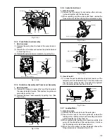
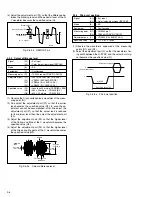
Fig. 3-3-2a EE Y level
H. rate
Y level
3.3.2 EE Y level
(1) Observe the Y OUT waveform at the measuring point (D).
(2) Record the signal (A2) in the mode (B1), and play back
the recorded signal.
(3) Press the channel buttons (+, –) simultaneously to enter
the manual tracking mode. This also brings tracking to
the center (centre).
(4) Set the VCR to the EVR mode by transmitting the code
(F1) from the Jig RCU.
(5) Set the EVR address to (F2) by pressing the button of
the digit-key remote controller.
(6) Adjust with the channel buttons (+, –) on the VCR (or on
the remote controller) so that the Y level of the Y OUT
waveform becomes the specified value (G).
(7) Release the EVR mode of the VCR by transmitting the
code (F1) from the Jig RCU again. (When the EVR mode
is released, the adjusted data is memorized.)
(8) Repeat steps (2) to (7) in the mode (B2).
3.3.3 PB Y level (S-VHS / VHS)
Signal
(A1)
• Ext. input
(A2)
• Color (colour) bar signal [PAL]
Mode
(B1)
• S-VHS SP
(B2)
• VHS SP
Equipment
(C)
• Oscilloscope
Measuring point
(D)
• Y OUT terminal (75
Ø
terminated)
EVR mode
(F1)
• Jig RCU: Code “57”
EVR address
(F2)
• A:11 (Press remote controller
“1” key twice)
Specified value
(G)
[HR-S6700MS]
• 1.00 ±0.05 Vp-p
[HR-S7700MS]
• 1.00 ±0.03 Vp-p
Adjustment tool
(H)
• Jig RCU [PTU94023B]
• Digit-key remote controller
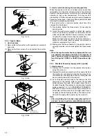
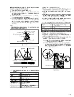
Fig. 3-3-3a PB Y level
H. rate
Y level
Note:
• The specified value (G) is just a reference value to be
obtained when the External S-Video (Y/C separated
video) signal is input. In actual adjustment, set it to
the value observed in step (3).
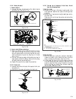
Fig. 3-3-1a D/A level
H. rate
Y level
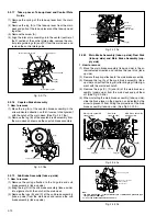
3.3.4 REC color (colour) level
Signal
(A1)
• Alignment tape(S-VHS,SP/LP,color(colour) bar)[MH-2H]
(A2)
• Ext. input
(A3)
• Color (colour) bar signal [PAL]
Mode
(B1)
• S-VHS SP
(B2)
• S-VHS LP
Equipment
(C)
• Oscilloscope
Measuring point (D1)
• TP106 (PB. FM)
(D2)
• PB color (colour) output of the LPF
External trigger
(E)
• TP111 (D.FF)
EVR mode
(F1)
• Jig RCU: Code “57”
EVR address
(F2)
• A:02 (Press remote controller
“0” and “2” keys)
Specified value
(G)
• SP: “B” x 125 ± 5%
• LP: “B” x 125 ± 5%
Adjustment tool
(H1)
• Jig RCU [PTU94023B]
(H2)
• Digit-key remote controller
(H3)
• LPF[PTU93006] (See Fig. 3-3-4a.)
Содержание HR-S6700MS
Страница 5: ......


