2-18
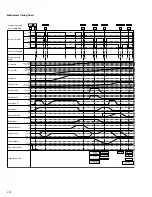
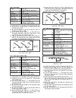
2.3.4 Standard tracking preset
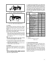
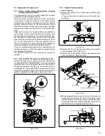
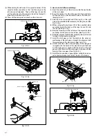
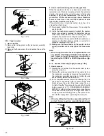
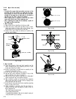
Fig. 2-3-3b
Fig. 2-3-3a
Alignment tape
[SP, stairstep]
played with the
SP head
Alignment tape
[EP(LP), stairstep]
played with the
EP(LP) head
Drum side
Control head position
Capstan side
X-value adjustment point
Maximum
Waveform output
[Perform adjustment steps (7) to (10) only for 2 Head
models equipped with LP mode.]
(7) Then play back the alignment tape (A2).
(8) Set the VCR to the manual tracking mode.
(9) Perform the tracking operation and make sure that the
V.PB FM waveform is at its maximum.
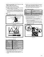
(10) If it is not at maximum, loosen the screws (4) and (5),
and turn the A/C head positioning tool to bring the A/C
head to a position, around where the waveform reaches
its maximum for the first time. Then tighten the screws
(4) and (5).
Note:
• After adjusting, always perform the confirmation and
re-adjustment of the item 2.3.4.
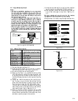
(1) Play back the alignment tape (A).
(2) Apply the external trigger signal to D.FF (E), to observe
the V.PB FM waveform at the measuring point (D).
(3) Confirm that the automatic tracking operation is com-
pleted.
Signal
(A)
•
Alignment tape(LP, stairstep, PAL) [MHPE-L]
Mode
(B)
•
PB
¥
Auto adjust
Equipment
(C)
•
Oscilloscope
Measuring point
(D)
•
TP106 (PB. FM)
External trigger
(E)
•
TP111 (D.FF)
Adjustment part
(F)
•
Jig RCU: Code “50”
Specified value
(G)
•
STOP mode
(Maximum V.PB FM waveform)
Adjustment tool
(H)
•
Jig RCU [PTU94023B]
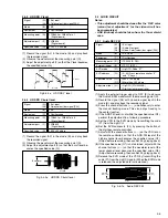
2.3.5 Tension pole position
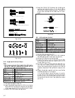
(1) Play back the back tension cassette gauge (A).
(2) Check that the indicated value on the left side gauge is
within the specified value (G).
(3) If the indicated value is not within the specified value (G),
perform the adjustment in a following procedure.
1) Set the VCR to the mechanism service mode. (See
SECTION 1 DISASSEMBLY.)
2) Set the VCR to the play back mode and adjust by turn-
ing adjustment pin to align the tension arm assembly
edge with the main deck hole (A) on the right edge
marker. (See Fig. 2-3-5a)
Signal
(A)
•
Back tension cassette gauge
[PUJ48076-2]
Mode
(B)
•
PB
Adjustment part
(F)
•
Adjust pin [Mechansim assembly]
Specified value
(G)
•
25 - 51 gf•cm (2.45 – 5
×
10
-3
Nm]
0.5 mm
Hole (A)
Edge
Marker
Tension arm
assembly
Adjust pin
Tension brake assembly
Tension arm assembly
A/C head positioning tool
Screw (4)
Screw (5)
Toward the drum
Toward the capstan
To the drum
A/C head
To the capstan
Head base
Fig. 2-3-5a
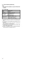
(4) Set the VCR to the Auto adjust mode by transmitting the
code (F) twice from the Jig RCU. When the VCR enters
the stop mode, the adjustment is completed.
(5) If the VCR enters the eject mode, perform adjustment for
the audio control head phase (X-value) again.

