


14
Operating Procedures
Operation
i
n Streaming/Record
Mode
In streaming/record mode, upon receiving
power the red Power LED on the back of the
unit illuminates solidly. After an initialization
period, the unit outputs live video via the
main fiber output and monitor output.
If no SD card is installed, the unit will
continue streaming live video and will accept
J* commands for image processing
adjustment. If no SD card is installed, the
green SD card LED will remain unlit.
Recording to SD Card
If an SD card is installed in streaming/record
mode, the onboard recording to SD card
function will be enabled. After the unit
receives power and while the unit initializes,
the green SD card LED will remain unlit.
When the unit is ready to record, the SD
card LED will illuminate solidly. Recording
can be started anytime the LED is solidly lit.
To
begin
recording, either:
Press the “Start/Stop” button on top of
unit
-OR-
Send the “Record Start” J* Command
.
While the unit is recording to the SD card, the
green SD card LED will blink once per
second.
To
stop
recording, either:
Press the “Start/Stop” button on top of
unit
-OR-
Send the “Record Start” J* Command
.
Once recording is stopped, the SD card LED
briefly turns off while processing is taking
place. The live outputs may momentarily
flicker. The SD card LED will re-illuminate
solidly to indicate the unit is ready to record
again. The video files on
t
he SD card
are
.MOV files and will be incremented by name
0000.MOV, 0001.MOV, etc.
Playback Mode is an optional function. For
implementation of this feature, please
contact AltaSens customer service.
Changing
Modes
Changing modes is an update function. Mode
changes will be enabled via J* Command sets.
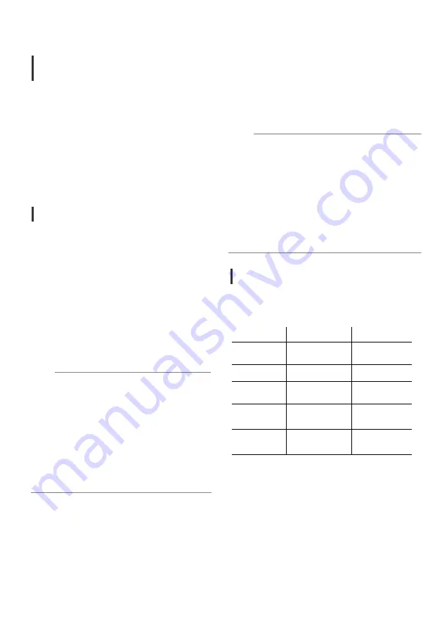
Indicator Light Behavior
The behavior of the LEDs on the camera are
summarized in the table below.
General
Operation
in
Playback
Mode
Note
:
If there is an error with recording, the SD
card LED will blink rapidly at a rate of two
times per second. In this case, power down
the unit and check the SD card files with a
computer or card reader. A file called
“mdat.dat” may be generated on the SD
card. In this case, clear this file and try
again. The SD card LED may also rapidly
blink at a rate of two times per second to
indicate the SD card being used is not
suitable or if the card is full
.
Note:
*
Option
MODE
POWER
LED
(RED) SD
CARD
LED
(GREEN)
ON
Power ON
Ready Recording /
Playback*
OFF
Power OFF
Under processing
OFF
(after inputted
Genlock source)
Lock waiting
status of Genlock ―
BLINKS
SLOWLY
(once every second)
Locked status
of Genlock
Recording /
Playback*
BLINKS
QUICKLY
(twice per second)
Genlock Error
(Check Genlock source
and reboot unit)
SD Card Error
(Check SD card data
after power-off)
Whenever
using an SD card, the SD
card must be inserted into the SD card
slot BEFORE turning on the unit. If
inserted after turning the unit on, the
SD card will not be detected.
Do not insert or remove an SD card
while the unit is powering on.
Whenever pressing button, firmly hold
the button down for approximately
one second then release.
Do not repeatedly press the button.
18
quad SDI output and monitor output.
Operating Procedures
Operation
i
n Streaming/Record
Mode
In streaming/record mode, upon receiving
power the red Power LED on the back of the
unit illuminates solidly. After an initialization
period, the unit outputs live video via the
main fiber output and monitor output.
If no SD card is installed, the unit will
continue streaming live video and will accept
J* commands for image processing
adjustment. If no SD card is installed, the
green SD card LED will remain unlit.
Recording to SD Card
If an SD card is installed in streaming/record
mode, the onboard recording to SD card
function will be enabled. After the unit
receives power and while the unit initializes,
the green SD card LED will remain unlit.
When the unit is ready to record, the SD
card LED will illuminate solidly. Recording
can be started anytime the LED is solidly lit.
To
begin
recording, either:
Press the “Start/Stop” button on top of
unit
-OR-
Send the “Record Start” J* Command
.
While the unit is recording to the SD card, the
green SD card LED will blink once per
second.
To
stop
recording, either:
Press the “Start/Stop” button on top of
unit
-OR-
Send the “Record Start” J* Command
.
Once recording is stopped, the SD card LED
briefly turns off while processing is taking
place. The live outputs may momentarily
flicker. The SD card LED will re-illuminate
solidly to indicate the unit is ready to record
again. The video files on
t
he SD card
are
.MOV files and will be incremented by name
0000.MOV, 0001.MOV, etc.
Playback Mode is an optional function. For
implementation of this feature, please
contact AltaSens customer service.
Changing
Modes
Changing modes is an update function. Mode
changes will be enabled via J* Command sets.
Indicator Light Behavior
The behavior of the LEDs on the camera are
summarized in the table below.
General
Operation
in
Playback
Mode
Note
:
If there is an error with recording, the SD
card LED will blink rapidly at a rate of two
times per second. In this case, power down
the unit and check the SD card files with a
computer or card reader. A file called
“mdat.dat” may be generated on the SD
card. In this case, clear this file and try
again. The SD card LED may also rapidly
blink at a rate of two times per second to
indicate the SD card being used is not
suitable or if the card is full
.
Note:
*
Option
MODE
POWER
LED
(RED) SD
CARD
LED
(GREEN)
ON
Power ON
Ready Recording /
Playback*
OFF
Power OFF
Under processing
OFF
(after inputted
Genlock source)
Lock waiting
status of Genlock ―
BLINKS
SLOWLY
(once every second)
Locked status
of Genlock
Recording /
Playback*
BLINKS
QUICKLY
(twice per second)
Genlock Error
(Check Genlock source
and reboot unit)
SD Card Error
(Check SD card data
after power-off)
Whenever
using an SD card, the SD
card must be inserted into the SD card
slot BEFORE turning on the unit. If
inserted after turning the unit on, the
SD card will not be detected.
Do not insert or remove an SD card
while the unit is powering on.
Whenever pressing button, firmly hold
the button down for approximately
one second then release.
Do not repeatedly press the button.
18
Ready Recording
Recording