


(No.YF087)1-13
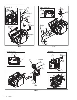
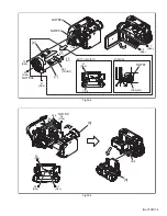
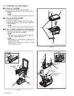
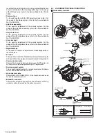
3.2.4 DISASSEMBLY of [9] OP BLOCK ASSMBLY/CCD BOARD ASSEMBLY
z
CAUTIONS
(1) During the procedure, be careful in handling the CCD
IMAGE SENSOR, OP LPF, and lens components.
Pay special attention not to soil, dust, or scratch the sur-
faces
If the surfaces are soiled with fingerprints and others,
they should be wiped away using silicon paper, clean
chamois or cleaning cloths.
(2) The CCD IMAGE SENSOR may be shipped with a
protective seal attached to the transmitting glass.
When replacing the CCD IMAGE SENSOR, do not peel
off the protective seal from the new part until immediately
before it is mounted in the OP BLOCK ASSEMBLY.
(3) The attachment direction of the OP LPF is so important
for installation that there may be a marking. Be careful
when removing the OP LPF, and make sure to attach it
exactly as same as its original status.
z
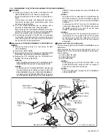
Disassembly of OP BLOCK ASSEMBLY/ CCD BOARD AS-
SEMBLY
(1) Remove the three screws (1-3), and remove the BKT
(OP) ASSEMBLY.
(2) Remove the HEAT SINK2.
(3) Remove the two screws (4,5), and remove the CCD BOARD
ASSEMBLY together with CCD BASE ASSEMBLY.
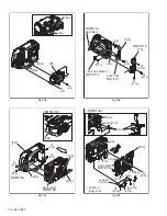
(4) Remove the LPF HOLDER from the CCD BASE AS-
SEMBLY, and remove the MASK.
NOTE 9a:
Since the MASK is between the LPF HOLDER and CCD
IMAGE SENSOR, be careful in handling the MASK.
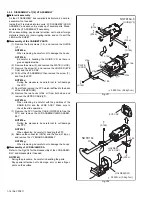
NOTE9b:
In removing the CCD IMAGE SENSOR, unsolder the
fourteen soldered parts (SD9a), and remove the CCD
BASE ASSEMBLY from the CCD BOARD ASSEMBLY.
In replacing the CCD IMAGE SENSOR, don't remove
the CCD IMAGE SENSOR from the CCD BASE AS-
SEMBLY. Instead, replace the whole CCD BASE AS-
SEMBLY.
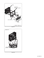
NOTE9c:
Since the OP LPF is inside the LPF HOLDER and the
OP LPF is attached to the LPF HOLDER by using the
SHEET, remove the OP LPF from the LPF HOLDER if
necessary.
In removing the OP LPF from the LPF HOLDER, be
careful not to damage the LPF HOLDER, and remove
the SHEET carefully if you want to use the same
SHEET in attachment procedure.
NOTE9d:
In removing the OP LPF, be careful of the direction of
its attachment. Since one side of the OP LPF is coated
for the purpose of protection, attach the OP LPF so
that the coated side faces the OP lens (a subject of
photograph).
z
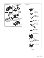
Replacement of service repair parts
The service repair parts for the OP BLOCK ASSEMBLY are as
listed below.
When replacing the parts, pay special attention not to cut/
damage the FPC or not to cause any damage by soldering (ex-
cessive heating).
(1) FOCUS MOTOR UNIT
(2) ZOOM MOTOR UNIT
(3) AUTO IRIS UNIT
NOTE9e:
When replacing the FOCUS MOTOR UNIT or the
ZOOM MOTOR UNIT, solder the FPC at a space of
about 0.5 mm above the terminal pin.
NOTE9f:
The AUTO IRIS UNIT includes the FPC ASSEMBLY
and two SENSORS.
Fig.3-2-4
SD9a
BKT(HEAT SINK)
HEAT SINK2
OP LPF
OP BLOCK
ASSY
OP
side
CCD
side
Blue
NOTE9e,f
AUTO IRIS UNIT
SENSOR
NOTE9e
FOCUS MOTOR
UNIT
NOTE9e
ZOOM MOTOR
UNIT
NOTE9c,d
NOTE9c
NOTE9c
NOTE9b
NOTE9a
NOTE9b
1
(S9a)
3
(S9a)
4
(S9b) 5
(S9b)
6
(S9e)
7
(S9e)
11
(S9d)
8
(S9e)
9
(S9c)
10
(S9c)
2
(S9a)
BKT(OP) ASSY
SHEET
LPF
HOLDER
MASK
CCD BASE ASSY
CCD BOARD ASSY
SD9b
: 0.118N
m (1.2kgf
cm)
MARK


