background image

15

ENGLISH

7

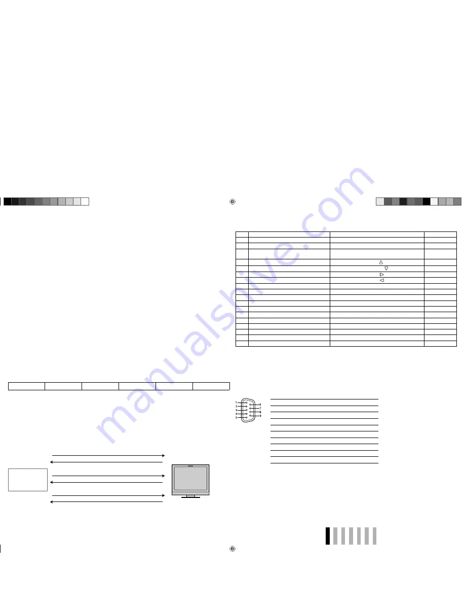
 Using the RS-232C system

You can control the monitor from a personal computer etc. via the RS-232C terminal.
•  Consult your dealer for the details of the external control specification.

<Communication specifications>

Baud Rate: 4800 bps
Data Bits: 8 bits
Parity: No parity
Stop Bits: 1 bit
Flow Control: No control
Communication Code: ASCII Code
•  Use a straight cable with a D-sub 9-pin connector (male for the monitor, female for the personal computer).

<Command outline>

All commands consist of the following segments.

Header

Monitor ID (00)

Command ID

Function

Data

Cr (0DH)

Header

“!”: Operation commands from the personal computer, etc. For details, see <Basic command list> on the right.
“?”: Reference commands from the personal computer, etc.
“@”: Status returns from the monitor

•  To start communication, send the connection command from the personal computer etc.
•  To terminate the communication, send the termination command from the personal computer etc.

Example of communication procedures

1

 Starting the communication: connection command 
(!00BCN1Cr)

3

 Selecting “SDI” input (!00BINACr)

5

 Terminating the communication: termination command 
(!00BCN0Cr)

6

 Monitor’s status (@00BOKCr)

4

 Monitor’s status (@00BOKCr)

2

 Monitor’s status (@00BOKCr)

PC, etc.

Monitor

This is a female 
terminal.

<Specifications of the RS-232C terminal>

Pin No.

Signal

1

NC

2

RXD

3

TXD

4

NC

5

GND

6

NC

7

RTS

8

CTS

9

NC

•  The 7th terminal and the 8th terminal are connected. 

Operation

1

  Set “TYPE SEL.” of “REMOTE SETTING” to “MAKE” or “TRIGGER” in the SET-UP MENU.

2

  Short-circuit the 7th pin terminal (ENABLE) to the 8th pin terminal (GND) so that the monitor can be controlled 

by the external control.

3

  When selecting “MAKE” system: Operate each function by short-circuiting the corresponding pin terminal to 

the 8th pin terminal (GND) or opening it.
When selecting “TRIGGER” system: Operate each function by pulse control, that is short-circuiting the 
corresponding pin terminal to the 8th pin terminal (GND) for about 1 second and opening it.

•  When changing the input with MAKE system, only one pin terminal must be short-circuited. (Other pin terminals 

must be opened.)

•  When selecting the “TRIGGER” system, you can operate only one function at a time. Operate the functions one 

by one.

<Basic command list>

No.

Commands

Functions

Data

1

!

0

0

B C N 1

Cr

Starts communication (connection)

No data

2

!

0

0

B C N 0

Cr

Terminates communication (termination)

No data

3

!

0

0

B M E N U Cr

Displays the MAIN MENU/Quits the menu 
operation

No data

4

!

0

0

B U P Cr

Moves the cursor upward ( )

No data

5

!

0

0

B D O W N Cr

Moves the cursor downward ( )

No data

6

!

0

0

B A D J

R Cr

Makes setting/adjustment ( )

No data

7

!

0

0

B A D J

L

Cr

Makes setting/adjustment ( )

No data

8

!

0

0

B S E T U P

Cr

Displays the SET-UP MENU

No data

9

!

0

0

B P W 1

Cr

Turns on the monitor

No data

10

!

0

0

B P W 0

Cr

Turns off the monitor (standby)

No data

11

!

0

0

B I

N A Cr

Selects “SDI” input

No data

12

!

0

0

B I

N B Cr

Selects “VIDEO/COMPO.” input

No data

13

!

0

0

B D I

S P Cr

Displays the status*

2

No data

14

!

0

0

B V P L

S Cr

Increases the volume level

No data

15

!

0

0

B V M N S Cr

Decrease the volume level

No data

16

!

0

0

B V O L

x

x*

1

Cr

Adjusts the volume level

00 – 30

17

!

0

0

B A M U T E

x

x*

1

Cr

Turns muting on/off

00: Off, 01: On

18

!

0

0

B A S P x

x*

1

Cr

Changes the aspect ratio

00: 4:3, 01: 16:9 

•  “Cr” is 0Dh.
•  The commands for starting communication (connection) (No. 1), terminating communication (termination) 

(No. 2), and turning on the monitor (No. 9) can be used while the monitor is off (on standby).

*

1

 Enter the appropriate data to “xx”.

*

2

 Displays the information shown when the button of the current input is pressed (

 “About the Status Display” on page 

7).

DT-V9L1D_EA_EN_R.indd   15

DT-V9L1D_EA_EN_R.indd   15

07.9.14   6:19:29 PM

07.9.14   6:19:29 PM

Содержание DT-V9L1D

Страница 1: ...To reduce the risk of electric shock Do not remove cover or back No user serviceable parts inside Refer servicing to qualified service personnel RISK OF ELECTRICAL SHOCK DO NOT OPEN The lightning flash with arrowhead symbol within an equilateral triangle is intended to alert the user to the presence of uninsulated dangerous voltage within the product s enclosure that may be of sufficient magnitude...

Страница 2: ...ing These openings must not be blocked or covered Never push objects of any kind into this product through openings as they may touch dangerous voltage points or short circuit the parts which could result in a fire or electric shock Never spill liquid of any kind on the product Never place anything on the product Placing liquids naked flames cloths paper etc on the product may cause a fire Do not ...

Страница 3: ... openings Use a vacuum cleaner to get rid of the dust around the intakes all the openings If a vacuum cleaner is not available use a cloth and wipe it off Leaving the dust around the intakes may prevent proper temperature control and cause damage to the product Information for Users on Disposal of Old Equipment European Union This symbol indicates that the electrical and electronic equipment shoul...

Страница 4: ...adjust the stand height You can select the stand height according to your preference higher position or lower position To change the stand height change the position of the screw hole used for attaching the stand When shipped from factory the stand is attached to the higher position Before adjusting the stand height set the monitor angle to 0 CAUTION Lay the monitor on a cloth with the LCD panel f...

Страница 5: ...anel use the two 100 mm pitch holes on the upper side using M4 x 10 mm screws not provided Bind the hooks on the rear panel of the monitor to a wall or a pillar using durable string Lower position Attachment screws Stand Hook and screws M4 x 10 mm not provided Hook not provided Monitor DT V9L1D_EA_EN_R indd 5 DT V9L1D_EA_EN_R indd 5 07 9 14 6 19 18 PM 07 9 14 6 19 18 PM ...

Страница 6: ...reen r FOCUS button lamp Helps to focus the picture When the FOCUS lamp lights PICTURE IMPROVEMENT is not displayed on the menu The settings of PICTURE IMPROVEMENT are ineffective page 10 t DYNAMIC button lamp Adjusts the picture to be suitable for a light place When the DYNAMIC lamp lights BACK LIGHT and PICTURE SUB ADJ are not displayed on the menu The setting of BACK LIGHT is ineffective page 1...

Страница 7: ...AUTO is selected for STATUS DISPLAY page 13 3 Source name assigned in CHARACTER SET Displayed when SOURCE ID is set to ON Displayed in large letters when STATUS DISPLAY is set to OFF or AUTO INFORMATION on page 13 Select the audio channels when the SDI is selected as a signal input and EMBEDDED AUDIO signals come in You have to choose a group of selectable audio channels before the channel selecti...

Страница 8: ...BEDDED AUDIO signals including up to 12 audio channels with the sampling frequency of 48 kHz OUT Output terminal for the HD SD SDI signals The signals are re clocked then emitted from this terminal The signals are emitted only when the monitor is on or in P SAVE power save mode 8 REMOTE terminal Terminal for controlling the monitor by an external control External Control on page 14 9 Carry handle ...

Страница 9: ...SC 4 B W60 2 PAL 5 480 59 94i 2 480 60i 6 576 50i 576 50i 7 480 59 94p 480 60p 8 576 50p 576 50p 9 720 60p 720 60p 10 720 59 94p 720 60p 11 720 50p 720 50p 12 1080 60i 1080 60i 13 1080 59 94i 1080 60i 14 1035 60i 1080 60i 3 3 15 1035 59 94i 1080 60i 4 4 16 1080 50i 1080 50i 17 1080 30psF 1080 60i 3 3 18 1080 25psF 1080 50i 5 5 19 1080 29 97psF 1080 60i 20 1080 24psF 1080 24psf 21 1080 23 97psF 108...

Страница 10: ...ker OFF 80 100 The area marker or the safety marker is displayed by using A MARKER or S MARKER button or external control Select either non R items or R items to activate by using external control External Control on page 14 When a picture is displayed in 4 3 aspect ratio the safety marker for the 4 3 area is displayed To display the safety marker for the area of a picture displayed in 16 9 aspect...

Страница 11: ...t levels W 100 white W 50 half tone REFERENCE LEVEL Select the standard input level indicated on the level meter 20dB 18dB OVER LEVEL Select the input level s lower limit indicated in red for the 3COLORS display 10dB 8dB 6dB 4dB 2dB BAR BRIGHTNESS Select the brightness of the level meter LOW HIGH SYNC FUNCTION Setting for the monitor performance when no signal comes in Item To do Setting value NO ...

Страница 12: ...ects the color temperature and adjusts the drive level of each color R G B Item To do Setting value COLOR TEMP Select the color temperature 6500K USER 9300K R DRIVE G DRIVE B DRIVE 3 Adjust the drive level of each color red green and blue 128 000 MAX sub menu Display the sub menu which enables you to adjust the items in WHITE BALANCE SET while viewing the actual picture reset Restore the default s...

Страница 13: ... information display of the monitor Item To do Setting value SOURCE ID Select if the name assigned in CHARACTER SET is displayed on the screen About the Information Display on page 7 OFF ON CHARACTER SET Assign a name to each video source as you like 10 characters at maximum You can also enter a name using the RS 232C system NOTE STATUS DISPLAY Select if the status of the current input and setting...

Страница 14: ...Adjusts the picture to be suitable for the light place Off On SDI Changes the input to SDI Invalid Valid VIDEO COMPO Changes the input to VIDEO COMPO Invalid Valid Display Functions to be controlled Opening Short circuiting ASPECT Changes the aspect ratio 4 3 16 9 TALLY SEL Selects the color of the tally lamp Green Red SOURCE ID SOURCE ID on page 13 Off On MUTING Muting on off Off On MARK SEL Sele...

Страница 15: ...h pin terminal GND or opening it When selecting TRIGGER system Operate each function by pulse control that is short circuiting the corresponding pin terminal to the 8th pin terminal GND for about 1 second and opening it When changing the input with MAKE system only one pin terminal must be short circuited Other pin terminals must be opened When selecting the TRIGGER system you can operate only one...

Страница 16: ... appear on the menu The items which are not available for the current input or the current input signal are not displayed on the menu Change the input or the input signal The items controlled by the MAKE system do not appear on the menu 14 Buttons on the monitor do not work Set CONTROL LOCK in the SET UP MENU to OFF 13 The following are not malfunctions When a still image is displayed for a long t...

Страница 17: ...omposed and may be slightly different from actual products Design and specifications are subject to change without notice All company names and product names mentioned herein are used for identification purposes only and may be the trademarks or registered trademarks of their respective companies 7 Input output terminals Video VIDEO COMPONENT IN OUT VBS Y Composite signal analog component Y signal...

Страница 18: ...osition at the lower position 176 186 116 Side view Rear view 202 100 75 37 5 When the stand is attached to the higher position When the stand is attached to the lower position 27 5 1 5 13 75 100 55 tapped hole 1 4 tapped hole 3 8 185 DT V9L1D_EA_EN_R indd 18 DT V9L1D_EA_EN_R indd 18 07 9 14 6 19 32 PM 07 9 14 6 19 32 PM ...

Отзывы: