background image

15

Precautions for Installation

Installing the Projector

Please read the following properly when installing the projector.

Installation Environment

Please do not install or use this projector in the follow-
ing places. The projector is a precision device and do-
ing so could cause a fire or malfunction.

• Where there is water, humidity or dust
• Where the projector may be subjected to oil, smoke or

cigarette smoke

• On a soft surface such as a carpet or cushion
• Where the projector may be subjected to direct sunlight
• Where temperature is high or low

Allowable operation temperature range : +5 °C to +35 °C
Allowable relative humidity range

: 20 % to 80 %

(no condensa-
tion)

Allowable storage temperature range

: –10 °C to +60 °C

• Any room in which there is smoke and grease

Even where smoke and grease levels are minimal, pro-
longed exposure will affect the projector. The projector
emits heat and optical components are cooled down by
taking in large amount of air.  The optical path being soiled
by grease/dirt can cause images to become dark and the
color projection to deteriorate. After soiling, removing
grease/dirt totally from the optical parts is not possible.

Precaution for Usage

This projector uses a light-source lamp which reaches
high temperatures when projecting.
Please DO NOT use it in the following ways as doing so
may result in fire or malfunction.

• Projecting images while the projector is on its side.
• Projecting images outside the specified angle.

Do not use the projector while it is set more than ±5°
horizontally (left/right), or more than ±25° vertically (up/
down). This could cause color variation or shorten the
lamp life.

• Use while blocking the exhaust vents.

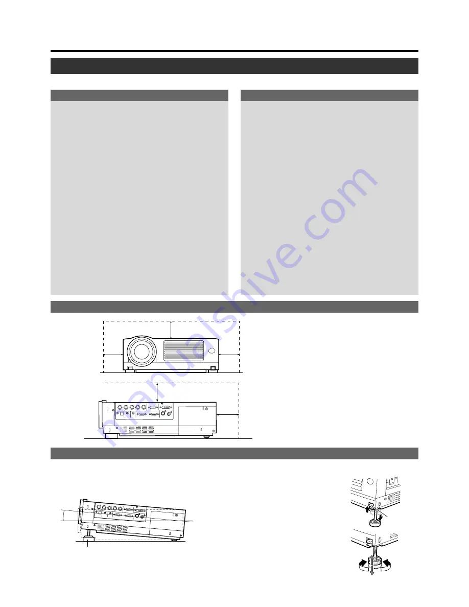
Adjusting the Inclination of the Projector

The vertical angle and leveling of the projector can be adjusted with the adjustable feet at the bottom of the projector.

Do not use a cover which may enclose the projector
air-tight or block the exhaust vents. Allow sufficient
space around the projector. When the projector is en-
closed in a space of the following dimensions, use an
air conditioner so that internal and external tempera-
tures are the same.

Adjusting the vertical angle of the projector

• While pushing the lever upward, raise the pro-

jector. The maximum extension is approximately
31 mm. To retract the foot, push the lever and
lower the projector slowly; the projector is fixed
at the position where you release the lever.

Adjusting the level of the projector minutely

• Lift the projector, rotate the front adjustable foot,

and adjust the horizontal angle until the projec-
tor is level.

Vertical angle adjustment range

Minimum Space Required

300 mm

300 mm

150 mm

150 mm

500 mm

Front Adjustable Foot

+6˚

Foot
Lever

Shorten

Extend

Содержание DLA-HX2E

Страница 1: ...PERATE V KEYSTONE H KEYSTONE SCREEN DIGITAL ZOOM FOCUS W S INSTRUCTIONS DLA HX2U DLA HX2E PROJECTOR DLA HX2U For customer Use Serial No Model No Enter below the Serial No which is located on the side panel of the cabinet Retain this information for future reference ...

Страница 2: ...ve force and uneven surfaces which may cause the prod uct and cart to overturn damaging equip ment or causing possible injury to the op erator IMPORTANT INFORMATION WARNING TO PREVENT FIRE OR SHOCK HAZARDS DO NOT EX POSE THIS APPLIANCE TO RAIN OR MOISTURE CAUTION To reduce the risk of electric shock do not remove cover Refer servicing to qualified service personnel This projector is equipped with ...

Страница 3: ...ce this indicates a need for service When replacement parts are required be sure the service technician has used replacement parts specified by the manu facturer or with same characteristics as the original part Un authorized substitutions may result in fire electric shock or other hazards Upon completion of any service or repairs to this product ask the service technician to perform safety checks...

Страница 4: ... If a new main plug has to be fitted then follow the instruc tion given below POWER CONNECTION United Kingdom only WARNING Do not cut off the main plug from this equipment If the plug fitted is not suitable for the power points in your home or the cable is too short to reach a power point then obtain an appropriate safety approved extension lead or adapter or consult your dealer If nonetheless the...

Страница 5: ...0 mA signal Short circuit will result in dam age fire or electrical shock Leave the connection of the screen to the installation contractor It will result in damage fire or electrical shock Care Dirt in the cabinet Please wipe the cabinet clean with a soft cloth In case of heavy soiling please wipe it with a damp cloth soaked with a neutral detergent Since the cabinet may in time get damaged or de...

Страница 6: ...ed Convenient Functions 28 Enlarging the Image 28 Turning Off Image and Sound 29 Displaying a Still Picture 29 Removing the Trapezoidal Distortion of the Image 30 Using the Quick Alignment function 31 Adjustments and Settings Using Menus 32 The Menu Structure 32 The Menu Operation Buttons 35 The Procedure for Menu Operation 36 The Menu Configuration 37 1 Image adj menu 37 2 Color temp menu 37 3 Se...

Страница 7: ...ly zoom the projected image on the screen page 26 1 Control Panel For details See Control Panel on the Projector page 10 11 2 AC Power Input Terminal This is where the supplied power cord is connected to page 24 3 Carrying Handle Use this handle when carrying the projector 4 Foot Lever for front adjustable foot Use when extending and retracting the front foot page 15 5 Lens The lens is a 1 3 x zoo...

Страница 8: ...e sensor is also provided at the front of the pro jector y Front Adjustable Foot for adjusting the height and angle It is set at the lowest position when shipped from the fac tory The foot can be adjusted to a maximum angle of 6 and a maximum length of 31 mm page 15 u Filter Cleans air drawn in from the air inlet Please clean the filter regularly with e g a vacuum cleaner page 50 i Rear Fixed Foot...

Страница 9: ...play output terminal of the computer to this terminal page 22 The menu screen for HDCP compatible signal input is the same as when PC input is selected 4 SCREEN TRIGGER Terminal The signal output for controlling roll up screen that sup ports SCREENTRIGGER Outputs DC 12 V max 100 mA when power is on Tip DC 12 V Sleeve Gnd Before using the supplied cable read How to use the SCREEN TRIGGER terminal c...

Страница 10: ...nd TEMP blinking 2 Circuits are not functioning properly Abnormal circuit functioning LAMP and OPERATE blinking alternately 2 Lamp cover has been removed TEMP blinking 2 Internal temperature is abnormally high Abnormal internal temperature TEMP and STAND BY blinking 2 Temperature at exhaust vents is high Abnormal external temperature All blinking 2 When inner fan has stopped fan lock V KEYSTONE PC...

Страница 11: ... this button to select a device connected to the PC1 PC2 or PC3 terminals page 26 w H KEYSTONE button Use this button to remove the horizontal trapezoidal distor tion of the image projected on the screen page 30 e V KEYSTONE button Use this button to remove the vertical trapezoidal distortion of the image projected on the screen page 30 r MENU button Use this button to enter or exit the menu mode ...

Страница 12: ...button p Cursor button u MENU button r V KEYSTONE button e H KEYSTONE button w PC button q VIDEO button 9 HIDE button 8 ENTER button 7 EXIT button t VOLUME button 2 OPERATE button 3 SCREEN button Not functional on this unit 4 DIGITAL ZOOM button 5 FREEZE button 1 Remote Control s signal transmitter y FOCUS button Not functional on this unit 6 QUICK ALIGN quick alignment button ...

Страница 13: ... sub menu to main menu When the main menu is displayed pressing this button will cause the menu to disappear page 35 8 ENTER button Press this button to show the next hierarchical menu For example from main menu to sub menu It is also used when ENTER is displayed against the item on the menu screen or to select the Reset menu page 35 9 HIDE button Use this button to temporarily halt the audio and ...

Страница 14: ...ew and old batteries Do not mix different types of batteries as they are differ ent in characteristics Place batteries so they match the polarities indicated on the cartridge Be sure to insert the minus end in first to avoid short circuiting Do not put batteries into a fire or try to recharge them Use only designated batteries Remove the batteries if the remote control is not to be used for a prol...

Страница 15: ...en projecting Please DO NOT use it in the following ways as doing so may result in fire or malfunction Projecting images while the projector is on its side Projecting images outside the specified angle Do not use the projector while it is set more than 5 horizontally left right or more than 25 vertically up down This could cause color variation or shorten the lamp life Use while blocking the exhau...

Страница 16: ...nt on places that will be subjected to knocks and vibrations As the depth of the screw holes is 10 mm use screws shorter than 10 mm but longer than 6 mm Otherwise the screws will damage the internal parts of the projector caus ing malfunction Install at a safe place in case this unit or a part of it may drop If the light source lamp is broken small pieces of glass from the mesh of the filter may a...

Страница 17: ...reen installation Relationship between projection distance and projection screen size Type 36 7 approx 93 2 cm Type 40 approx 101 6 cm Type 60 approx 152 4 cm Type 80 approx 203 2 cm Type 100 approx 254 0 cm Type 120 approx 304 8 cm Type 140 approx 355 6 cm Type 160 approx 406 4 cm Type 180 approx 457 2 cm Type 200 approx 508 0 cm Type 220 approx 558 8 cm Type 240 approx 609 6 cm Type 260 approx 6...

Страница 18: ...he range of the remote cable length Warranty is not extended to the case where an extension cord is used Installing the Projector Q U I C K A L I G N P C V I D E O V O L U M E P R E S E T H I D E M E N U E X I T F R E E Z E O P E R A T E V K E Y S T O N E H K E Y S T O N E S C R E E N D I G I T A L Z O O M F O C U S W S E N T E R 20 20 30 A B 30 Q U I C K A L I G N P C V I D E O V O L U M E P R E ...

Страница 19: ...g frequency 15 kHz 120 kHz Vertical scanning frequency 24 Hz 25 Hz 30 Hz 50 Hz 120 Hz Be sure that the computer used meets the following conditions The computer has a video signal output port Confirm if the computer has a video signal output port by consulting the computer s manual The video signal output port is generally called RGB port monitor port or video port In the case where the computer c...

Страница 20: ...d normally When a signal other than those listed above is input the image could be partially erased or unwanted folds over the image may appear Some signals other than those listed above can be displayed However they may require adjustment Some of the signals listed above may require adjustment depending on the video board used Composite sync Cs and G on Sync signals cannot sometimes be handled de...

Страница 21: ...ble and PC Audio cables are not supplied Connecting to Video Devices Before connection be sure to turn off both the projector and the device Image input Connect to component signal output device DTV format signal output device HDCP compatible video signal output de vice etc When the PC2 input terminal is used the PC2 BNC item in Options menu must be correctly set page 39 When the PC3 input termina...

Страница 22: ...EMOTE SCREEN TRIGGER RS 232C OUT RS 232C IN Y C VIDEO CONTROL VIDEO IN Thoroughly read the manuals that come with the computer used Prepare cables for connecting the devices There are some notebook type computers that do not allow the computer s LCD to work if an external display device is connected With such computers the LCD display and external display output need to be switched To PC2 To DVI T...

Страница 23: ...ion please contact your authorized dealer Control from external device Connect to Computer Connect to the IN terminal of third projector Connection for controlling more than one projector By using the CONTROL terminal more than one projector can be controlled simultaneously by one computer Connect these projectors in series by connecting the OUT terminal of the first projector to the IN terminal o...

Страница 24: ...hen not using devices remove the power plug from the wall outlets Do not use power cords other than those supplied Do not use a power voltage different from that which is indicated Do not cut tear or modify the power cords Also do not put a heavy object on heat or stretch the power cords otherwise they may be damaged Do not insert or pull out the plugs with a wet hand When using the projector remo...

Страница 25: ...function When the lamp is turned on it will slowly become brighter It will take more than a minute for the brightness to stabilize VIDEO Image from the input VIDEO terminal on the right hand side of projector will be projected Y C Image from the input Y C ter minal on the right hand side of the projector will be projected MENU V KEYSTONE PC LAMP H KEYSTONE VOL EXIT ENTER VIDEO TEMP STAND BY OPERAT...

Страница 26: ... is input to the selected input terminal the mes sage No Input is displayed on the screen page 53 When the PC2 input terminal is used PC2 BNC must be se lected from the Options item in the main menu page 39 3 Adjusting the Zoom Ring the screen size To enlarge the screen size Turn the zoom ring towards the Wide side To reduce the screen size Turn the zoom ring towards Tele side 4 Adjusting the Focu...

Страница 27: ... shorten the life of the lamp and cause a malfunction MENU V KEYSTONE PC LAMP H KEYSTONE VOL EXIT ENTER VIDEO TEMP STAND BY OPERATE 5 QUICK ALIGN PC VIDEO VOLUME PRESET HIDE ENTER MENU EXIT FREEZE OPERATE V KEYSTONE H KEYSTONE SCREEN DIGITAL ZOOM FOCUS W S 5 6 1 6 1 VOL VOLUME Audio Vol 12 Audio Vol 12 6 Power Off 1 Press the OPERATE button on the projector or the OP ERATE button on the remote con...

Страница 28: ...een can be enlarged in 8 stages by pressing this button including the standard size To reduce the size of the image 2 While Digital zoom display appears on the screen you can move the zoomed image with the cursor buttons on the remote control To see the upper part of zoomed image Press To see the lower part of zoomed image Press To see the right part of zoomed image Press To see the left part of z...

Страница 29: ...isplayed on the top right cor ner of the screen To de freeze the image When you press the FREEZE button again the image de freezes and resumes Notes After de freezing a still image note that the projector will not play the image that comes immediately after Should you want to play the image that comes immediately after that at which the FREEZE button was pressed please pause the image using the co...

Страница 30: ...ensation It is recommended to place the projector perpen dicularly to the screen Depending on the signal inputted the keystone adjustment range may narrow or parts of the image may disappear This is not a malfunction Interference patterns may appear on the screen when adjusting the keystone This is not a malfunction To restore the original set value press the PRESET button when adjusting the V KEY...

Страница 31: ...k when signals are input via a VIDEO IN terminal The VIDEO or Y C input terminal When input signal from PC3 input terminal is received QUICK ALIGN is displayed but it is not functional The Quick Alignment function This automatically adjusts Horiz disp pos Vert disp pos Phase Tracking etc Using the Quick Alignment function for automatic adjustments Please use with bright still pictures This functio...

Страница 32: ...et up Logo Options Language Information A GREEN BLUE RED GB R Color temp D65 HIGH User Image adj Set up Logo Options Language Information A GB R OFF ON OFF ON OFF ON 9600 RGB YPbPr Image adj Set up Logo Options Language Information A GB R 19200 PC HDCP 1280 1400 Sleep time min Menu color PC2 BNC DIST SCART RS 232C bps SXGA PC3 60 15 30 OFF Color profile Menu display Line display Flip H Flip V Page...

Страница 33: ...e NTSC PAL EXIT Image adj Set up Logo Options Language Information A GB R Image adj Set up Logo Options Language Information Input Switcher Resolution Frequency H Frequency V Lamp time Deutsch Español Italiano Français Português A Image adj Set up Logo Options Language Information OFF ON OFF ON OFF ON 9600 RGB YPbPr Image adj Set up Logo Options Language Information A GB R 19200 PC HDCP 1280 1400 ...

Страница 34: ...adj Set up Logo Options Language Information Input Switcher Lamp time OFF ON OFF ON OFF ON 9600 RGB YPbPr Image adj Set up Logo Options Language Information A GB R 19200 1280 1400 Deutsch Español Italiano Français Português A Image adj Set up Logo Options Language Information English PC HDCP 60 15 30 OFF Sleep time min Menu color PC2 BNC DIST SCART RS 232C bps SXGA PC3 Image adj Set up Logo Option...

Страница 35: ...splayed Press to return to the previous menu While the main menu is displayed press to exit the menu mode Select menu items and ad justment items Perform setting of the se lected adjustment item Some items are not possi ble for setting The adjusted value will be reflected to the image im mediately QUICK ALIGN PC VIDEO VOLUME PRESET HIDE ENTER MENU EXIT FREEZE OPERATE V KEYSTONE H KEYSTONE SCREEN D...

Страница 36: ...put or PC input is selected or when there is no image signal inputted For details please see The Menu Configuration on the next page E g Main menu when video input is selected Image adj Alternatively press ENTER When the item in the image adjustment menu against which ENTER is indicated is selected either it will shift to the set up screen or the item command will be executed E g Set up menu when ...

Страница 37: ...t dims and brightens Set the position of the clamp pulse to Back porch BP or Sync tip ST Normally BP is used Values ST BP BP Adjustment item press Adjustment content press Contrast Adjusts the contrast of the picture image Range of values 30 30 0 Brightness Adjusts the brightness of the picture im age Range of values 30 30 0 Color Adjusts the color density of the picture image Range of values 30 3...

Страница 38: ... Position Adjusts the position of the image and menu display Press the ENTER button to enter the Position menu 4 Sync level Although the inputted image signal is adjusted so that synchronization occurs automatically this changes by changing this setup Setting can be made by selecting Low weaker Std factory set or High stronger Values Low Std High Std 4 Position menu You can adjust the menu display...

Страница 39: ...language in this language menu with the CURSOR buttons Setting value Japanese English Deutsch German Español Spanish Italiano Italian Français French Português Portuguese and Korean English Some words in the menu and proper nouns such as VIDEO NTSC QUICK ALIGN are shown only in English p Capture start The status of capture is displayed in bold Capt in prog approx 2min The image is being read into ...

Страница 40: ...ion Displays the resolution of the inputted sig nal Horizontal x vertical Some inputted signals cannot be dis played correctly Frequency H Displays the horizontal frequency of the inputted signal Frequency V Displays the vertical frequency of the in putted signal Lamp time Displays the number of accumulated used hours of the current light source lamp When no image signal is inputted Input Displays...

Страница 41: ...elow the screen such as in DVD software QUICK ALIGN PC VIDEO VOLUME PRESET HIDE ENTER MENU EXIT FREEZE OPERATE V KEYSTONE H KEYSTONE SCREEN DIGITAL ZOOM FOCUS W S MENU V KEYSTONE PC LAMP H KEYSTONE VOL MENU EXIT ENTER VIDEO TEMP STAND BY OPERATE 3 4 3 4 2 2 3 4 3 4 A 12 12 1 12 12 ENTER ENTER Image adj Set up Logo Options Language Information Contrast Brightness Color Tint Sharpness Color temp Res...

Страница 42: ...image 16 9 Zoom Image loss No Aspect ratio Landscape Image is stretched horizontally Image loss Yes Aspect ratio Same Image is chopped off at the upper and lower portion Image loss Yes Aspect ratio Portrait Image is stretched vertically and chopped off at the upper and lower portion Image loss No Aspect ratio Landscape Image is stretched horizontally Image loss No Aspect ratio Same Image cannot be...

Страница 43: ... ZOOM FOCUS W S MENU V KEYSTONE PC LAMP H KEYSTONE VOL MENU EXIT ENTER VIDEO TEMP STAND BY OPERATE 3 4 3 4 2 2 3 4 3 4 A 12 12 1 12 12 ENTER ENTER Image adj Set up Logo Options Language Information Contrast Brightness Color Tint Sharpness Color temp Reset A GB R Image adj Set up Logo Options Language Information ENTER ENTER Low Std High ST BP 12 123 Position Tracking Phase Resize Clamp Sync level ...

Страница 44: ...nal is PC3 and with HDCP signal input Image loss No Aspect ratio Same Optimum image Image cannot be largely projected 1 1 Panel Aspect Zoom Image loss Yes Aspect ratio Same There may be cases where only the upper left portion of the image is projected Image loss No Aspect ratio Same Image cannot be largely projected Image loss No Aspect ratio Landscape Image is stretched horizontally Image loss No...

Страница 45: ...r logo 2 Press the MENU button The main menu appears on the screen 3 Select Logo with the cursor buttons 4 Press the ENTER or the right cursor button The Logo menu appears on the screen 5 Select Capture menu with the cursor buttons and press ENTER 6 The captured picture appears on the screen The captured picture i e your logo with a frame appears on the screen MENU V KEYSTONE H KEYSTONE VOL EXIT E...

Страница 46: ...ls cannot be captured while others of the same size can be MENU V KEYSTONE H KEYSTONE VOL EXIT ENTER 7 12 12 QUICK ALIGN PC VIDEO VOLUME PRESET HIDE ENTER MENU EXIT FREEZE OPERATE V KEYSTONE H KEYSTONE SCREEN DIGITAL ZOOM FOCUS W S 7 12 12 Capt in prog approx 2min Signal can not be captured Reduce capt size Image adj Set up Logo Options Language Information A ENTER ENTER 12 12 G B R Capture menu M...

Страница 47: ...osen the screws and lift up the handle Loosen the two screws with a ª screwdriver When the lamp time exceeds 2000 hours The lamp indicator on the projector blinks Warning and Lamp replacement appear on the screen the word Warning blinks To cancel the message press the EXIT button However the same message will appear again every one hour Once the lamp time exceeds 2000 hours and the projec tor is e...

Страница 48: ...the two claws in first and then ensure that the protruding part found on the reverse side of the cover fits snugly into the hole of the main unit As this protrusion acts as a switch misfitting leads to power not being able to flow in Caution Neither touches the glass surface of the lamp di rectly with your hand nor stains it If you touch it with a bare hand oil or other substances on your hand may...

Страница 49: ...art If the display of the accumulated lamp time has reached 2000 hours the projector will not work lamp does not light up unless the lamp time is reset To ensure the lamp time has been reset The lamp time can be checked via the Lamp time item in the Infor mation menu page 32 33 34 40 Caution for reset work Reset the lamp time only when you have replaced the lamp Never reset it while the lamp is st...

Страница 50: ...ou purchased the projector The air inlet filter on the right side cannot be removed Please clean this filter regularly using for example a vacuum cleaner 1 Pull out the power cord from the wall outlet After the projector goes into the stand by state with the STAND BY indicator on pull out the power cord from the wall outlet 2 Remove the filter When removing the lower filter Withdraw the lower filt...

Страница 51: ...irmly After the projector goes into the stand by state with the STAND BY indicator on un plug from the main power outlet close the light source lamp cover correctly and plug in again After the projector goes into the stand by state with the STAND BY indicator on un plug from the main power outlet insert the filter properly and plug in again After the projector goes into the stand by state with the...

Страница 52: ...us with the focus ring of the lens Set the projector at the correct distance Adjust Tracking and Phase using the menu Adjust Brightness using the menu Adjust picture quality using the menu Set the Decoder to AUTO or the correct dedicated decoder If the problem is not rectified after setting to AUTO set to forced dedicated mode Check if the signal is appropriate scanning frequency etc and input the...

Страница 53: ...inal name is shown above the mes sage Check the input image signal source The frequency of the input video signal is out of range Please ensure the frequency level of the input video signals is within the projector s specifications What to do when these messages are displayed Message Cause Contents PC 1 No Input PC 1 Frequency of input signal is out of range ...

Страница 54: ...ed lamp time reaches 2000 hours The message can be cleared by pressing the EXIT button However the same message will re appear every hour Once the projector is turned off it cannot be turned on again if the accumu lated lamp time has exceeded 2000 hours When the accumulated lamp time reaches 2010 hours the projector shuts down and cannot be turned on again Replace the light source lamp and reset t...

Страница 55: ...rt according to the basic operation procedures If the warning indication is observed again wait for the cooling fan to stop Plug out the power cord with STAND BY indicator lights up and call your dealer for repair For details on individually blinking indicators please see page 47 About warning indicators If something abnormal has occurred in the projector the warning mode will be set in and the ty...

Страница 56: ... AUDIO 1 line RCApin X 1 Y C VIDEO PC1 PC2 PC3 0 5 V rms high impedance CONTROL RS 232C 2 lines D sub 9pin x1 External controller IN 1 system OUT 1 system REMOTE 1 line stereo mini jack x1 remote control Output terminals SCREEN TRIGGER terminal DC Power Jack Tip DC 12 V max 100 mA Sleeve Gnd Power requirements AC 100 V 240 V AC 50 Hz 60 Hz Power consumption 3 4 A 100 V AC 1 42 A 240 V AC Operation...

Страница 57: ...Specifications Front Bottom Top Side 181 20 67 5 298 2 7 298 38 2 300 360 8 2 89 267 115 9 65 4 15 25 56 109 292 36 2 92 5 M6 Depth 10 mm Center of lens Attachment screw should be more than 6 mm but less than 10 mm in length ...

Страница 58: ... Pin number 9 10 11 12 13 14 15 Signal name N C GND SYNC GND N C H SYNC V SYNC N C Signal name Red Green Blue N C N C GND Red GND Green GND Blue Pin number 1 2 3 4 5 6 7 8 9 10 11 12 Signal name TMDS data 2 TMDS data 2 TMDS data 2 4 shield N C N C DDC clock DDC data N C TMDS data 1 TMDS data 1 TMDS data 1 3 shield N C Pin number 13 14 15 16 17 18 19 20 21 22 23 24 Signal name N C TMDS 5 V power su...

Страница 59: ...R Designates the terminal of the data 0Dh is not necessary for Asking command 2 2 Response data format Upon executing a control command it has received the projector sends back the following response data to the computer Header Designates the head of data 40h Fetches data from the projector ID 1 The identification number of the projector Manufacturer set value 1 SP Designates the delimiter for ID ...

Страница 60: ...004 Hex 30h 30h 30h 30h 30h 30h 30h 31h 30h 30h 30h 32h 30h 30h 30h 34h Meaning Stand by mode Power on mode Cool down mode Emergency mode Operation mode Only Asking command is possible Function Command Asking Data type Power on ELSE Numeric Value ON OFF Special Data OPERATE HIDE Right Left reversal Top Bottom inversion Input switch Operation mode U0F U00 U17 U18 U1A Z03 X X X X X X X X X X X X X X...

Страница 61: ...61 Memo ...

Страница 62: ...DLA HX2U DLA HX2E Printed in Japan 1004 SW VP 2004 Victor Company of Japan Limited PROJECTOR ...

Отзывы: