


1-8 (No.49787B)
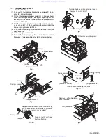
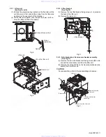
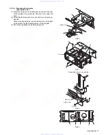
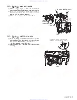
3.1.3
Removing the fittings
(See Fig.10)
(1) Remove the fixing screw
F
.
(2) Unhook the two catches
a
on the top edge of the fitting, then
unhook the two catches
b
at the left / right bottom edges.
Fig.10
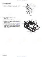
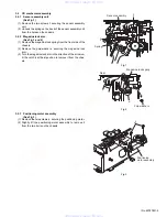
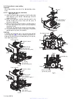
3.1.4
Removing the main PCB assembly
(See Fig.11)
(1) Remove the power IC fixing screw
G
.
(2) Remove the four screws
H
securing the main board as-
sembly.
(3) Disconnect position motor wire connector
CN504
from the
main board assembly.
(4) Disconnect sensor board assembly wire connector
CN601
from the main board assembly.
(5) Remove the flexible ribbon wire from
CN502
on the
traverse mechanism board assembly. When reinstalling
the board boards, refer to the reassembling procedures for
protecting switches, etc.
Fig.11
Catches a
Catches b
Fitting
F
H
CN601
CN504
CN502
H
G
H
Main board
www. xiaoyu163. com
QQ 376315150
9
9
2
8
9
4
2
9
8
TEL 13942296513
9
9
2
8
9
4
2
9
8
0
5
1
5
1
3
6
7
3
Q
Q
TEL 13942296513 QQ 376315150 892498299
TEL 13942296513 QQ 376315150 892498299