


(No.49787B)1-15
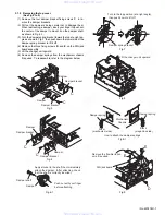
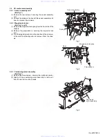
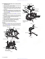
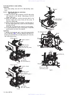
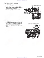
3.2.13.2 Mounting the lifter unit
(See Fig.24 to 26)
(1) Insert the shafts
f
of the traverse mechanism assembly into
the slide grooves
g
on the lifter unit.
(2) Shift the hook of the lifter unit to the edge, and shift the slid-
ing lever inside the side bracket unit to the edge as well.
(3) With each hole and lever shifted to the edge, mount the lift-
er unit and side bracket unit from the side. (Check each at-
tached section, and check that the two shafts
h
of the lifter
unit are correctly inserted into the holes
i
of the side bracket
unit. After mounting, check that the levers move together. )
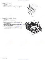
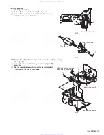
(4) Turn the lifter unit upside down.As shown in Fig. 35, slide
the lever 30mm away from the edge, then mount the lifter
bracket assembly.
Fig.24
Fig.25
Fig.26
f
f
f
h
Attach
i
g
g
g
Lifter unit
M
Side bracket
Traverse mechanism
assembly
Shift inside by approx. 30 mm
Expanded view
Lifter bracket
www. xiaoyu163. com
QQ 376315150
9
9
2
8
9
4
2
9
8
TEL 13942296513
9
9
2
8
9
4
2
9
8
0
5
1
5
1
3
6
7
3
Q
Q
TEL 13942296513 QQ 376315150 892498299
TEL 13942296513 QQ 376315150 892498299