background image

FS-SD1000R

1-7

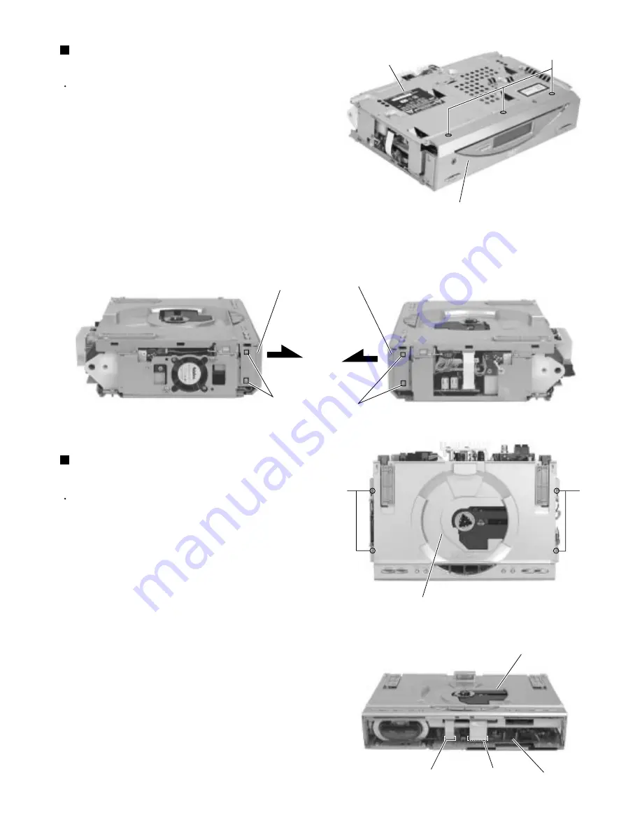
Prior to performing the following procedure, remove 
the CD door, the rear cover and the side covers.

Remove the three screws E  on the bottom of the 
body.

Release two joints a and two joints b on both sides 
of the body using a screwdriver and remove the front 
panel assembly toward the front.

1.

2.

Removing the front panel assembly 

(See Fig.4 to 6)

Prior to performing the following procedure, remove 
the CD door, the rear cover, the side covers and the 
front panel assembly.

Disconnect the card wire from connector CN104 and 
CN105 of the main board in the front part of the 
body. Disconnect the card wire from CN101 of the 
main board on the right side, and the wire from 
CN705 and CN708 of the CD mechanism base 
assembly respectively.

Remove the four screws F  attaching the CD 
mechanism base assembly on the upper side of the 
body. Remove the screw I  attaching the earth 
terminal on the right side.

1.

2.

Removing the CD mechanism base 
assembly (See Fig.7 to 14)

Fig.4

Fig.6

Fig.5

E

Front panel assembly

(Left side)

(Right side)

Front panel assembly

Joints a

Joints b

Bottom

Fig.7

Fig.8

F

F

CD mechanism base assembly

CD mechanism base assembly

Main bard

CN105

CN104

Front panel assembly

Содержание CA-FSSD1000R

Страница 1: ...y method Maintenance of laser pickup Replacement of laser pickup Flow of functional operation unit TOC read Method of connecting treatment device wire Description of major ICs 1 2 1 4 1 5 1 6 1 17 1 17 1 18 1 19 1 20 32 This model not have adjustment REMOTE CONTROL RM SFSSD1000J STANDBY ON DIMMER SLEEP DISPLAY FM MODE CD PROGRAM DOOR SLIDE AUTO PRESET REPEAT RANDOM BASS TREBLE CANCEL UP SET DOWN M...

Страница 2: ...cabinet screw heads headphone jack control shafts etc to be sure the product is safe to operate without danger of electrical shock Do not use a line isolation transformer during this check Plug the AC line cord directly into the AC outlet Using a Leakage Current Tester measure the leakage current from each exposed metal parts of the cabinet particularly any exposed metal part having a return path ...

Страница 3: ... damage resulting therefrom 3 Essential safety critical components are identified by on the Parts List and by shading on the schematics and must never be replaced by parts other than those listed in the manual Please note however that many electrical and mechanical parts in the product have special safety related characteristics These characteristics are often not evident from visual inspection Pa...

Страница 4: ...ålning är denna del är öppnad och spårren är urkopplad Betrakta ej strålen VARO Avattaessa ja suojalukitus ohitettaessa olet alttiina näkymättömälle lasersäteilylle Älä katso säteeseen ADVARSEL Usynlig laserstråling ved åbning når sikkerhedsafbrydere er ude af funktion Undgå udsættelse for stråling ADVARSEL Usynlig laserstråling ved åpning når sikkerhetsbryteren er avslott unngå utsettelse for str...

Страница 5: ... to their original condition Refer to the text 2 Do not use a tester to check the condition of the laser diode in the optical pickup The tester s internal power source can easily destroy the laser diode 4 Handling the traverse unit optical pickup 1 Do not subject the traverse unit optical pickup to strong shocks as it is a sensitive complex unit 2 Cut off the shorted part of the flexible cable usi...

Страница 6: ...n the upper side of the body 1 Removing the CD door See Fig 1 Prior to performing the following procedure remove the CD door the rear cover Remove the four screws D attaching the side covers on the bottom of the body Move the left cover backward and remove outward Also remove the right cover in the same way 1 2 Removing the right and left covers See Fig 3 Disassembly method Fig 1 Fig 2 Fig 3 B B B...

Страница 7: ... the card wire from connector CN104 and CN105 of the main board in the front part of the body Disconnect the card wire from CN101 of the main board on the right side and the wire from CN705 and CN708 of the CD mechanism base assembly respectively Remove the four screws F attaching the CD mechanism base assembly on the upper side of the body Remove the screw I attaching the earth terminal on the ri...

Страница 8: ...e door arms pull the CD mechanism base assembly toward the front and disconnect the wire from connector CN804 on the left side of the door arm board Pull out the CD mechanism base assembly toward the front 3 4 5 6 Fig 9 Fig 10 Fig 11 F I CD mechanism base assembly Main board CN101 CN708 F CD mechanism base assembly CN804 CD mechanism base assembly CN301 G Power amplifier board Fig 13 Gear a Fig 12...

Страница 9: ...board R and L See Fig 15 to 20 When the door arms incline the door arm assembly and the door arm board R and L may not be removed ATTENTION Remove the four screws H on the upper side and the one screw I on the left side of the body Remove the four screws J attaching the door arm board L and R on both sides of the door arm assembly 2 3 Fig 15 Fig 16 Fig 18 Fig 20 Fig 17 Fig 19 Door arm Door arm boa...

Страница 10: ...mbly 1 2 Removing the transformer assembly See Fig 21 Prior to performing the following procedure remove the CD mechanism base assembly and the door arm assembly Disconnect the wires from connector CN106 on the main board and release it from the cord stopper Remove the three screws N attaching the gear motor assembly Remove the gear motor assembly with the gear motor stopper Remove the belt from t...

Страница 11: ...e front panel board inside the front panel assembly 1 Removing the front panel board See Fig 28 Front panel assembly Prior to performing the following procedure remove the CD mechanism base assembly and the door arm assembly To facilitate operation process remove the gear motor assembly before performing the following procedure Disconnect the wires from connector CN102 CN106 CN191 CN192 CN193 and ...

Страница 12: ...e assembly and disconnect the wires from connector CN703 and CN706 on the CD mechanism board Remove the seven screws U attaching the CD mechanism cover and the CD mechanism board Turn back the CD mechanism assembly and detach the CD mechanism cover while pulling the CD mechanism assembly outward to release the two joint tabs marked c 1 2 3 Removing the CD mechanism board CD mechanism assembly See ...

Страница 13: ...rom the three shafts of the CD mechanism cover 4 5 6 When reassembling confirm that the cushion of the CD mechanism assembly is reattached to the three shafts ATTENTION Remove the CD mechanism board from the CD mechanism cover 7 Fig 33 Fig 32 CD mechanism assembly CD mechanism cover CD mechanism board CN605 Cushion Cushion CD mechanism cover CD mechanism board Shafts Short circuit land Sub board C...

Страница 14: ...connector CN502 on the jack board Remove the six screws W attaching the switch board 1 2 Removing the switch board See Fig 35 Disconnect the harness from connector CN706 on the CD mechanism board on the underside of the CD mechanism base assembly Push inward the two tabs d attaching the LED board case and release them Pull out the LED board from the LED board case 1 2 3 Removing the LED board See ...

Страница 15: ...Remove the three screws B on the amplifier 1 2 Amplifier Removing the cover See Fig 2 Cut off the band under the input amplifier filter board assembly Disconnect the harness from connector CN251 Remove the two screws C attaching the input amplifier filter board assembly Pull and disconnect connector CN211 from the body 1 2 3 Removing the Input amplifier filter board assembly See Fig 3 Fig 1 Amplif...

Страница 16: ...bly Disconnect the harness from connector CN291 on the amplifier board assembly and from CN299 on the power board assembly Remove the four screws G attaching the transformer assembly 1 2 3 Removing the transformer assembly See Fig 6 Disconnect the harness from connector CN299 on the power board assembly and cut off the band Remove the three screws H assembly Remove the cord stopper 1 2 3 Removing ...

Страница 17: ...fe of the laser diode has expired the following symptoms will appear 1 The level of RF output EFM output amplitude of eye pattern will below Is the level of RFOUT under 1 25V 0 22Vp p Replace it NO YES O K 3 Semi fixed resistor on the APC PC board The semi fixed resistor on the APC printed circuit board which is attached to the pickup is used to adjust the laser power Since this adjustment should ...

Страница 18: ... Automatic measurement of TE amplitude and automatic tuning of TE balance 500mv div 2ms div Fig 1 Approx 3sec pin 25 of IC601 TE Approx 1 8V VREF Tracking error waveform at TOC reading Power ON Play Key Confirm that the Focus error S cuve signal at the pin28 of IC603 is approx 2Vp p Confirm that the signal from pin24 IC603 is 0V as a accelerated pulse during approx 400ms Confirm the waveform of th...

Страница 19: ...efore removing the pickup Then carry out the replacement Refer to Disassembling and assembling the traverse unit When the KSM 900AAH mechanism is used the expansion cable is used as follows EXTFSSD5 JIG extension wire QUQB12 0840CJ 8pin card wire QUQB12 0940DJ 9pin card wire QUQB12 1840DJ 18pin card wire QUQB12 1640DJ 16pin card wire EXTKSM900 JIG Sub board ...

Страница 20: ... BYTE RAM 1024 BYTE 16 bit TIMER EVENT COUNTER 8 bit TIMER EVENT COUNTER50 PORT0 PORT1 PORT2 PORT3 PORT4 PORT5 PORT6 PORT7 EXTERNAL ACCESS SYSTEM CONTROL 8 bit TIMER EVENT COUNTER51 SERIAL INTERFACE30 SERIAL INTERFACE31 UART0 INTERRUPT CONTROL A D CONVERTER VDD0 VDD1 Vss0 Vss1 IC BUZZER OUTPUT CLOCK OUTPUT CONTROL WATCHDOG TIMER WATCH TIMER ...

Страница 21: ...ction for safety CD door motor lock detection signal input Version detection Reference voltage input for A D converter Analog power supply for A D converter System reset signal input Sub clock Sub clock signal input 32 768kHz Connect to VSS0 or VSS1 Main clock Main clock signal input 4 19MHz Ground without port section Remote controller signal input RDS clock signal input Sub clock OSC control sig...

Страница 22: ...F TEOUT TEN FEN FEOUT GCTL FBAL TBAL E F D B C A Earth terminal VREF output terminal VDET output terminal VDET input terminal TE Amp output terminal TE Amp reversing input terminal FE Amp reversing input terminal FE Amp output terminal Terminal GCTL APC FBAL control terminal TBAL control terminal Tracking signal input terminal 1 Tracking signal input terminal 2 Focus signal input terminal 4 Focus ...

Страница 23: ...peration amplifier 1 Pin layout 2 Block diagram Q19 Q17 Q16 OTHER CH R9 R6 R8 R7 R5 R4 R3 R2 R1 D1 C1 Q18 Q13 Q11 Q8 Q5 Vcc VEE OUTPUT IN IN Q1 Q3 Q4 Q2 C2 Q9 Q6 Q7 Q10 Q12 Q14 Q15 Q114 GP1U271X IC801 Receiver for remote controller GND B P F VCC Vout Amp Limiter Integrator Comparator Demodulator ...

Страница 24: ...1 BASS22 OUT1 BASS11 BASS12 MID11 MID12 MID21 MID22 TRE2 TRE1 VOL1 VOL2 GOUT2 GOUT1 CH1 input pin A CH2 input pin A CH1 input pin B CH2 input pin B CH1 input pin C CH2 input pin C CH1 input pin D CH2 input pin D CH1 input pin E CH2 input pin E Microphone input pin Filter pin Ground pin Serial data latch receiving pin Serial clock receiving pin Power supply pin CH2 output pin CH2 bass filter settin...

Страница 25: ...orting protection circuit Overvoltage thermal protection circuit Input amplifier BEEP amplifier Input amplifier A B D C Nonlinear output stage Amplifier output stage SW drive A B C D H L S STBY D C PRE GND IN 1 IN 2 ON TIME BEEP Vcc Vcc SW SW B SW E SW OUT1 SW OUT2 SW GND OUT 1 OUT 2 N C OUT 1 OUT 2 PWR GND 1 PWR GND 2 H L S Higher Level signal selector Ripple filter LA4905 IC301 2ch BTL power IC ...

Страница 26: ...puts ON OFF BTL AMP 1 input pin BTL AMP 1 input pin For gain adjustment BTL AMP 1 input pin Non inverting side BTL AMP 1 input pin Inverting side BTL AMP 2 input pin Inverting side BTL AMP 2 input pin Non inverting side BTL AMP 2 input pin For gain adjustment BTL AMP 2 input pin External transistor collector PNP connection 5V power supply output External transistor PNP base connection Reset output...

Страница 27: ...t output port Input output port Data input output Function IF counter signal input IF signal output Not use AM Local OSC signal output FM Local OSC signal input Power suplly VDD 4 5 5 5V When power ON Reset circuit move PLL charge pump output H Local OSC frequency Height than Reference frequency L Low Agreement Height impedance Input for active lowpassfilter of PLL Output for active lowpassfilter ...

Страница 28: ...ck pulse output Tracking drive output Focus drive output Reference voltage input pin for D A output block TVD FOD FBA TBAL Focus Balance adjust signal output Tracking Balance adjust signal output Focus error signal input Analog input Tracking error signal input Analog input RF envelope signal input Analog input Vibration detect signal input H detect Off track signal input H off track Track cross s...

Страница 29: ...TR8 TR12 TR10 TR11 TR23 TR24 TR22 TR21 R14 R16 R19 TR20 R15 R16 R17 TR19 R18 C6 D7 TR14 TR13 C3 R12 TR16 TR15 TR17 R13 TR31 R31 D31 D32 TR32 R32 Comparator Comparator D34 D36 D35 D33 SUB 1 3 5 4 2 7 6 8 21 22 9 16 10 14 15 11 12 13 17 18 19 20 STK411 210E IC221 Power amplifier 1 Block diagram ...

Страница 30: ...Lch Voltage controlled terminal When voltage of terminal is MONO at H and ST at L When voltage of terminal is AM at H and FM at L Multi plex signal input AM detection signal output FM detection signal output Bypass to FMIF Input of AMIF signal Fixed voltage output terminal Output terminal for AM mixer Input of FMIF signal Function Function 2 Pin function 1 Block d iagrams 24 23 22 21 20 19 18 17 1...

Страница 31: ... CW CCW CCW CW BRAKE 2 10 1 Standby circuit Heat interception IN1 IN2 GND 5 M OUT1 OUT2 8 3 9 7 Vref Vs Vcc TA8409F W IC108 Motor driver 1 Block diagram 2 Pin function A OUT 1 A IN 2 A IN 3 V 4 8 V 7 B OUT 6 B IN 5 B IN A B NJM4580D D IC101 IC211 IC213 Dual ope amp 1 Pin layout Block diagram ...

Страница 32: ... R2 R8 R7 R5 R6 Q16 R11 R10 C1 3 INPUT 1 OUTPUT 2 COMMON KIA78S06P T IC702 Regulator 1 Pin layout 2 Block diagram 1 2 3 1 2 3 4 5 6 7 14 13 12 11 10 9 8 1A 1Y 2A 2Y 3A 3Y GND VCC 6A 6Y 5A 5Y 4A 4Y A L H Y H L TC74HCU04AP IC251 2ch NOR gate 1 Pin layout Block diagram 2 True table ...

Страница 33: ...FS SD1000R 1 33 M E M O ...

Страница 34: ...200106 VICTOR COMPANY OF JAPAN LIMITED AUDIO COMMUNICATION BUSINESS DIVISION PERSONAL MOBILE NETWORK BUSINESS UNIT 10 1 1chome Ohwatari machi Maebashi city 371 8543 Japan No 20976 FS SD1000R ...

Страница 35: ...8 CN193 W3901 CN102 W3001 CN104 CN105 W5081 CN701 CN702 CN703 CN603 CN605 CN606 W8004 W8003 W8002 CN502 CN291 CN299 CN281 CN221 CN261 CN211 CN215 J2102 J2101 CN501 J5303 J5031 J5302 M AC IN S W SPEAKER T209 SPEAKER AC IN H P MUTING OUT1 OUT1 OUT2 OUT2 SIGL SIGR POUT SMUTE SIGL SIGR POUT SMUTE SMUTE SIGL SIGR MT0 MT1 MTS LOCK SIGL SIGR AMOSC IFOUT OSCOUT AMOSCOUT IFCONT Lch Rch E1 E2 PRI1 PRI2 TUNE...

Страница 36: ...929 R1938 C5308 C5307 C5309 R1921 4 7 50 2 2K 2 2K 6 8K QGA2501C1 07 6 8K LA4905 6A10E2 0 012 2SC2412K R X MTZJ3 9B T2 10 35 QGF1201F3 09 QQR0797 002 10 35 QQR0797 002 0 012 0 012 0 012 QNZ0136 001Z 2 2K 2 2K 0 001 QNC0030 001 QNC0052 001 0 0027 0 0027 22 16 22 16 82K 82K QNC0030 001 27K QGF1201F3 08 27K 6 8K 6 8K BD3861FS X QNS0047 001 QNS0047 001 4 7 50 22 16 22 16 4 7 50 4 7 50 4 7 50 4 7 50 22...

Страница 37: ...48RPMFA QQR0601 001Z 2 2K 2 2K 1K 10K 10K 91 NI 180k 270k 0 022 0 022 470P 39K 47K 8 2K 330P 0 027 0 022 6 8K NI 330P 43K 4 7k 180K 4 7K 39K 9 1K 3 9K 0 022 4 7K 12P QAX0413 001Z 15P 470 390K 2 7K QGF1006F1 16W 470P 0 022 GP1FA550TZ 100P QGF1008F1 16 2SC2060 QR T 0 0033 0 0033 0 001 220 10 0 1 1SS355 X 22 1K 0 1 390P 390P 0 001 NI NI 1M LA6541 X AN22000A 100 6 3 1K 0 0 01 0 0022 1 5M 150K 0 0022 1...

Страница 38: ...1 001 2SD2114K VW X 220 10 220 10 QQL231K 470Y QQL231K 470Y 22 QGB1216K1 14S 2 7K QGB1216J1 14S KIA78S06P T 1SS133 T2 DTA114EKA X 2SD2114K VW X 2 7K 22 10K 10K 10K 100K DTC144EKA X 10K 10 16 2SA1037AK R X 10K NI SPR 39MVWF NI DTC114EKA X 560 2 2K QQR0601 001Z QNS0162 001 2 2K 47K NI 2SC2412K R X 10K 2SC2412K R X UPD78F0034GKB19 2 2K 1K 1K 100 1K 1K 1K 1K 2 2K 2 2K 2 2K 2 2K 2 2K 2 2K 1K 10K 1K 2 2...

Страница 39: ...37 C41 R21 L5 C15 C18 QAU0034 001 0 001 LC72136N 2 2K 4 7K 1K 2 2K 1K 1K 1K 4 7K 2 2K QQL231K 2R7Y 0 018 1K 1 8K 0 001 10 16 0 01 0 047 QQL231K 221Y 0 001 10K 82 100P 0 047 2 2 50 100P 0 0012 0 001 0 047 1K QQR0794 001 680P 15K 12P 47 16 15P 220P 12P 10K 39P 10K TA2057N 12P 10K 330 0 0039 1K 47K BU1923 100 10 4 7K 10K 4 7 50 15P 3 9k 10 QAX0420 001 QAX0421 001 3 3K QQR0793 001 330 0 001 0 001 3 3 ...

Страница 40: ...2228 D2212 D2211 R2233 C2214 C2253 C2121 C2231 R2128 R2127 C2110 C2106 CN299 NJM4580D D NJM4580D D NJM4580D D NJM4580D D NJM4580D D 68K 56K 56K 8 2K 150K 150K 150K 5 6K 220K 2 2K 3 3K 5 6K 5 6K 10K 15K 12K 39K 0 0056 0 01 0 01 10 50 10 50 10KB QGA7901C1 02 150K 0 033 0 047 0 1 TC74HCU04AP TC74HCU04AP TC74HCU04AP TC74HCU04AP QGA3901C1 02 10 50 10 50 470 6 3 22 25 100 25 1M 4 7K 22 1K 100K 1M 2 2K 1...

Страница 41: ...7 R1217 C1210 C1110 R1218 R1118 T3A IC2 C1 C6 C21 C12 C11 C4 C35 C37 C33 C36 C32 B117 C39 C45 C43 C44 C40 C41 C42 C49 C50 C95 C53 B137 C65 C60 C62 C63 C61 C68 C69 C70 C71 C31 CF2 CF3 C14 B131 CF4 IC1 C67 R29 L4 R43 R44 R45 L10 B133 Q2 Q3 Q4 Q1 Q6 B114 B132 R68 R2 R1 R12 R13 R15 R16 R11 R10 R21 R22 R31 R30 R26 R27 C92 R36 R37 C66 WR1 R65 R48 R84 R60 R66 R52 L11 R54 R55 R56 R57 R46 WR2 B134 R74 T1 C...

Страница 42: ...6 C6097 C6098 C6099 C6140 C6154 C6156 C6157 C6158 C6159 C6199 C6201 C6202 C6203 C6251 C6252 C7001 C7002 C7003 C7004 C7005 C7006 C7007 C7008 C7009 C7010 C7011 C7012 C7013 C7014 C7015 C7016 C7017 C7018 C7019 C7020 C7021 C7022 C7023 C7112 C7114 C7119 C7120 CN603 CN605 CN701 CN702 CN703 CN704 CN705 CN706 CN707 CN708 D6001 D6031 D6032 D6033 D6061 D6062 D6063 D6500 D7001 D7002 D7003 D7004 D7005 D7006 D7...

Страница 43: ... R2220 R2221 R2222 R2223 R2224 R2225 R2226 R2227 R2228 R2229 R2233 R2701 R2702 R2703 R2704 R2705 C2237 R2801 R2802 R2803 R2811 R2812 R2921 R2922 RY281 Z292 Z293 Z294 Z295 B7852 B7204 C2223 B7206 B7207 B7851 B7020 B7009 B7010 B7008 B7004 B7003 C2222 B7011 B7952 C2236 B7404 B7211 EP281 R2254 B7304 B7403 B7016 B7951 W2801 B7208 B7702 B7953 B7701 B7202 B7007 B7402 C2252 B7502 B7012 W2912 B7205 B7301 B...

Страница 44: ...507 D2508 D2509 D2510 D2511 IC261 IC211 IC212 IC213 IC251 J2101 Q2101 Q2102 Q2501 Q2502 R2101 R2102 R2103 R2104 R2105 R2106 R2107 R2108 R2109 R2110 R2111 R2112 R2113 R2114 R2115 R2116 R2117 R2118 R2119 R2120 R2121 R2122 R2123 R2124 R2125 R2126 R2501 R2502 R2503 R2504 R2505 R2506 R2507 R2512 R2513 R2514 R2515 R2516 R2517 R2518 R2519 R2520 R2521 R2522 R2523 S2101 VR211 CN211 B8201 B8004 B8005 B8009 ...

Страница 45: ...ervice parts Contents Exploded view of general assembly and parts list CA FSSD1000R Exploded view of general assembly and parts list SP PW1000 Electrical parts list Packing materials and accessories parts list FS SD1000R 3 2 3 5 3 7 3 16 Area suffix B U K E Continental Europe EN Northern Europe ...

Страница 46: ...1 DC MOTOR 1 21 QYSPSP3004Z SCREW 2 DC MOTOR M BASE 22 QYSBST3006Z T SCREW 3 MOTER B BOTTOM 23 LV31688 001A WHEEL STOPPER 1 ABS 24 LV41524 001A MAIN GEAR 1 POM 25 LV31689 002A SHAFT 1 1 COST DOWN 26 LV31690 001A ARM 2 ABS 27 LV31691 001A G WHEEL L 1 POM 28 LV31692 001A G WHEEL R 1 POM 29 LV31693 001A G GEAR L 1 PBT 30 LV31694 001A G GEAR R 1 PBT 31 LV31695 001A ARM GEAR L 1 PBT 32 LV31696 001A ARM...

Страница 47: ...3006Z T SCREW 4 BOTTOM C TOP 75 GN30008 003A FUNC BTN ASSY 1 76 QYSDSF2606Z SCREW 1 SPK PWB TOP 77 QYSDSF2606Z SCREW 2 JACK PWB TOP 78 LV31686 001A LED BOX 1 MIPS SPRAY 79 LV41521 001A LED COVER 1 ABS 80 LV31704 001A IC HOLDER 1 AL T2 81 QYSBSF3010Z TAPPING SCREW 2 IC IC HOLDER 82 LV31849 001A HEAT SINK 1 AL T2 83 QYSBSF3010Z TAPPING SCREW 2 DIODE H SINK2 84 LV31705 002A HEAT SINK 1 AL 85 LV31850 ...

Страница 48: ...44 41 41 26 41 43 45 40 25 24 31 38 34 34 36 39 38 13 10 10 10 78 79 14 54 54 58 58 57 57 57 57 10 98 99 19 17 18 22 23 22 22 20 21 43 40 15 16 102 29 27 37 34 34 38 32 30 35 41 41 44 44 41 42 38 84 82 86 81 80 83 85 83 93 55 95 94 94 94 94 95 95 93 93 87 39 26 28 42 61 96 97 51 53 53 62 60 52 59 63 54 100 101 104 103 105 56 56 65 65 65 49 48 48 86 91 91 89 89 88 Speaker jack board Line board LCD ...

Страница 49: ...ploded view of general assembly and parts list Block No M M M 2 SP PW1000 34 37 38 40 41 39 36 42 9 9 10 10 22 7 8 11 13 27 16 15 24 14 4 15 16 28 29 25 25 20 23 5 19 2 14 3 20 17 31 30 21 17 19 26 18 J V C 1 33 32 12 6 ...

Страница 50: ...QYSBSGY3008E TAP SCREW 3 FOR SPK TERMINA 19 QYSDSA4020M TAP SCREW 11 20 QYSBST3006Z T SCREW 4 FOR POWER SW 21 QYSBSG3016Z T SCREW 2 FOR POWER IC 22 QYSBSF4012Z SCREW 2 23 QYSBSG3010Z T SCREW 2 24 QHS3771 108 CORD STOPPER A 1 25 E407321 002SM PUSH BUTTON 2 26 LV30734 002A KNOB 1 27 QQT0265 003 POWER TRANS A 1 T2901 28 QMPN090 200 JC POWER CORD B A 1 QMPK090 205 JN POWER CORD A 1 29 QMF51E2 1R0 J1 F...

Страница 51: ...1X C CAPACITOR C 89 NCB21HK 102X C CAPACITOR C 90 NCB21HK 103X C CAPACITOR C 91 NCB21HK 103X C CAPACITOR C 92 NCB21HK 103X C CAPACITOR C 93 NCB21HK 103X C CAPACITOR C 95 NCB21HK 102X C CAPACITOR CF 1 QAX0420 001 C FILTER FM IF CF 2 QAX0421 001 C FILTER FM IF CF 3 QAX0418 001Z C FILTER CF 4 QAX0409 001 CERA LOCK CN101 QGF1201F3 08 CONNECTOR TO FUNC CN102 QGA2501C1 06 6P CONNECTOR TO PO CN103 QGB121...

Страница 52: ...I DIODE A LV D1911 MTZJ6 8A T2 ZENER DIODE BL8 D1912 MTZJ10A T2 ZENER DIODE A BL8 D1913 MTZJ6 8B T2 ZENER DIODE A US5V D1914 MTZJ3 9B T2 ZENER DIODE TU5 D1915 1SS133 T2 SI DIODE TU5 D1916 1SS133 T2 SI DIODE TU5 D1917 1SS133 T2 SI DIODE RY D8001 SPR 39MVWF LED POWER STANDBY D8002 1SS133 T2 SI DIODE D8021 SELU1E50CM LED D8022 SELU1E50CM LED D8025 MTZJ10C T2 Z DIODE D8031 SELU1E56BM LED D8032 SELU1E5...

Страница 53: ...91 QSK0116 001 RELAY A VH R1101 NRSA02J 122X MG RESISTOR TU R1102 NRSA02J 562X MG RESISTOR TU R1103 NRSA02J 682X MG RESISTOR AHB R1104 NRSA02J 272X MG RESISTOR LPF R1106 NRSA02J 1R0X MG RESISTOR AHB R1108 NRSA02J 273X MG RESISTOR AHB R1110 NRSA02J 823X MG RESISTOR AHB R1112 NRSA02J 332X MG RESISTOR HP R1113 NRSA02J 563X MG RESISTOR HP R1114 NRSA02J 102X MG RESISTOR HP R1115 NRSA02J 561X MG RESISTO...

Страница 54: ...R R8031 NRSA02J 431X MG RESISTOR R8032 NRSA02J 431X MG RESISTOR R8051 NRSA02J 101X MG RESISTOR R8052 NRSA02J 272X MG RESISTOR R8053 NRSA02J 332X MG RESISTOR R8054 NRSA02J 562X MG RESISTOR R8055 NRSA02J 123X MG RESISTOR R8056 NRSA02J 393X MG RESISTOR R8057 NRSA02J 101X MG RESISTOR R8058 NRSA02J 272X MG RESISTOR R8059 NRSA02J 332X MG RESISTOR R8060 NRSA02J 562X MG RESISTOR R8061 NRSA02J 123X MG RESI...

Страница 55: ...31HJ 471X C CAPACITOR C6020 NDC31HJ 331X C CAPACITOR C6021 NCB31HK 152X C CAPACITOR C6022 QEKC0JM 476Z E CAPACITOR 47MF 20 6 3V C6023 NCB31CK 273X C CAPACITOR C6028 NCB31CK 473X C CAPACITOR C6029 QEKC0JM 107Z E CAPACITOR 100MF 20 6 3V C6031 QEKC1AM 227Z E CAPACITOR 220MF 20 10V C6032 QEKC0JM 107Z E CAPACITOR 100MF 20 6 3V C6033 QEKC1CM 106Z E CAPACITOR 10MF 20 16V C6034 QFN31HJ 103Z M CAPACITOR 01...

Страница 56: ... LINE IN R5203 NRSA63J 302X MG RESISTOR CD IN R5204 NRSA63J 1R0X MG RESISTOR FUC OUT R5205 NRSA63J 473X MG RESISTOR LINE OUT R5206 NRSA63J 392X MG RESISTOR LINE OUT R5207 NRSA63J 102X MG RESISTOR LINE OUT R5208 NRSA63J 222X MG RESISTOR L O MUTE R5209 NRSA63J 103X MG RESISTOR S W OUT R5210 NRSA63J 332X MG RESISTOR BASS R5301 NRSA63J 223X MG RESISTOR L O MUTE D R5302 NRSA63J 222X MG RESISTOR S W MUT...

Страница 57: ...ISTOR R7038 NRSA63J 103X MG RESISTOR VERSION R7040 NRSA63J 102X MG RESISTOR R7041 NRSA63J 103X MG RESISTOR R7042 NRSA63J 103X MG RESISTOR R7043 NRSA63J 103X MG RESISTOR R7044 NRSA63J 103X MG RESISTOR R7045 NRSA63J 222X MG RESISTOR R7046 NRSA63J 222X MG RESISTOR R7047 NRSA63J 102X MG RESISTOR FOR RDS R7048 NRSA63J 102X MG RESISTOR R7049 NRSA63J 102X MG RESISTOR R7050 NRSA63J 104X MG RESISTOR R7051 ...

Страница 58: ...CBB1HK 101Y C CAPACITOR 100PF 10 50V C2506 QETN1HM 106Z E CAPACITOR 10MF 20 50V C2507 QDYB1CM 103Y C CAPACITOR C2508 QETN0JM 477Z E CAPACITOR 470MF 20 6 3V C2701 QTE1C06 476Z E CAPACITOR C2702 QTE1C06 476Z E CAPACITOR C2703 QTE1E28 107Z E CAPACITOR C2704 QTE1E28 107Z E CAPACITOR C2801 QETN1HM 105Z E CAPACITOR 1 0MF 20 50V C2901 QCZ9104 472 C CAPACITOR A 4700PF C2911 QEZ0223 478 E CAPACITER A 4700M...

Страница 59: ...3Y C RESISTOR 56K 5 1 4W R2228 QRE141J 102Y C RESISTOR 1 0K 5 1 4W R2229 QRT01DJ R33X UNF MF RESISTOR A 5 1 1W R2233 QRE141J 472Y C RESISTOR 4 7K 5 1 4W R2252 QRE141J 100Y C RESISTOR 10 5 1 4W R2501 QRE141J 102Y C RESISTOR 1 0K 5 1 4W R2502 QRE141J 123Y C RESISTOR 12K 5 1 4W R2503 QRE141J 104Y C RESISTOR 100K 5 1 4W R2504 QRE141J 102Y C RESISTOR 1 0K 5 1 4W R2505 QRE141J 104Y C RESISTOR 100K 5 1 4...

Страница 60: ... Packing materials and accessories parts list Block No M M M Block No M M M 4 3 P10 P3 P1 A1 A2 A3 A9 A8 A7 A6 P2 A4 A5 P7 P4 P5 P9 P8 P15 P17 P11 P12 A10 P14 P13 P16 P6 P18 P21 P21 P19 P20 P20 A14 A12 A13 A11 P22 P22 ...

Страница 61: ...5 01 TOP CUSHION 1 SP FSSD1000 P 19 80 000 455 11 BOTTOM CUSHION 1 SP FSSD1000 P 20 85 000 416 11 POLY BAG 1 SP FSSD1000 P 21 85 000 357 31 POLY BAG 1 SP FSSD1000 P 22 85 000 357 51 POLY BAG 1 SP FSSD1000 Item Parts number Parts name Area A Parts list Accessories Q ty Description Block No M4MM A 1 QAM0199 001 PIN CABLE 1 A 2 LVT0685 008A INST BOOK E 1 GER FRE DUT LVT0685 009A INST BOOK EN 1 GER FR...

Отзывы: