1-10
RC-BZ5LB/BZ5RD
RC-BZ6BU
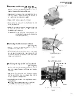
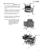
Prior to performing the following procedure, remove
the CD / cassette and amplifier assembly, the CD
cover and door unit and disconnect the harnesses
connected to the key switch / display board.
The cassette mechanism cover is still attached.
Push inward the locking tabs e on both sides of the
cassette mechanism cover and remove the
mechanism cover in the direction of the arrow.
Disconnect the harnesses from connector CN301
and CN308 on the main board.
Remove the upper two screws F and the cassette
mechanism assembly toward the front.
1.
2.
3.
Removing the cassette mechanism
assembly (See Fig.13 to 15)
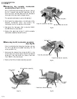
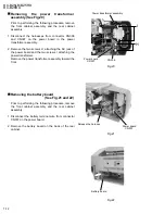
Prior to performing the following procedure, remove
the CD / cassette and amplifier assembly, the CD
cover and door unit.
Disconnect the harness from connector P011 on the
motor board in the lower part of the CD mechanism
assembly. Then disconnect the pickup card wire
from CN601 on the main board.
Remove the CD mechanism assembly upward.
1.
2.
Removing the CD mechanism assembly
(See Fig.16)
Fig.13
Fig.14
Fig.15
Fig.16
Cassette mechanism assembly
Cassette mechanism
cover
Cassette mechanism assembly
Cassette mechanism cover
Cassette mechanism assembly
Main board
CN308
CN301
F
F
Motor board
P011
CD mechanism assembly
Main board
CN601
Locking tab e
Locking tab e

