background image

1-14 (No.YA225)

4.6.4 DEFLECTION CIRCUIT ADJUSTMENT

Item

Measuring 

instrument

Test point

Adjustment part

Description

VERTICAL 
POSITION
adjustment

Signal 
generator

Remote
control unit

030

 (REGULAR)

040

 (PANORAMIC)

050

 (14:9 ZOOM)

060

 (16:9 ZOOM)

070

 (16:9 ZOOM

SUBTITLE)

110

 (FULL)

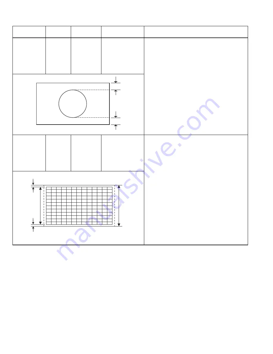
(1) Receive a PAL circle pattern signal.
(2) Enter the SERVICE MODE.
(3) Select ADJUST MENU.
(4) Select 

030

.

(5) Adjust 

030

 to make 

A=B

.

(6) Check and readjust 

030

 item if the adjustment

becomes improper after some other geometric
adjustments are done.

(7) Select 

040

 (PANORAMIC).

(8) Adjust 

040

 in the same procedure.

(9) Select 

050

 (14:9 ZOOM).

(10) Adjust 

050

 in the same procedure.

(11) Select 

060

 (16:9 ZOOM).

(12) Adjust 

060

 in the same procedure.

(13) Select 

070

 (16:9 ZOOM SUBTITLE).

(14) Adjust 

070

 in the same procedure.

(15) Select 

110

 (FULL).

(16) Adjust 

110

 in the same procedure.

VERTICAL
SIZE
adjustment

Signal 
generator

Remote
control unit

031

 (REGULAR)

041

 (PANORAMIC)

051

 (14:9 ZOOM)

061

 (16:9 ZOOM)

071

 (16:9 ZOOM

SUBTITLE)

111

 (FULL)

(1) Receive a PAL crosshatch signal.
(2) Enter the SERVICE MODE.
(3) Select ADJUST MENU.
(4) Select 

031

 (REGULAR).

(5) Adjust 

031

 until horizontal black lines on both the

upper and lower part of the crosshatch pattern
become very closeted the upper and lower
horizontal sides of picture size and nearly about to
disappear.

(6) Check and readjust 

031

 item if the adjustment

becomes improper after some other geometric
adjustments are done.

(7) Select 

041

 (PANORAMIC).

(8) Adjust 

041

 in the same procedure.

(9) Select 

051

 (14:9 ZOOM).

(10) Adjust 

051

 in the same procedure.

(11) Select 

061

 (16:9 ZOOM).

(12) Adjust 

061

 in the same procedure.

(13) Select 

071

 (16:9 ZOOM SUBTITLE).

(14) Adjust 

071

 in the same procedure.

(15) Select 

111

 (FULL).

(16) Adjust 

111

 in the same procedure.

A

B

Screen

size

Very close

Very close

Picture

size

100%

Содержание AV-28F3SJ

Страница 1: ...005 Victor Company of Japan Limited No YA225 2005 2 FLAT COLOUR TELEVISION YA225 2005 2 AV 28F3SJ TABLE OF CONTENTS 1 PRECAUTION 1 4 2 SPECIFIC SERVICE INSTRUCTIONS 1 5 3 DISASSEMBLY 1 6 4 ADJUSTMENT 1 10 5 TROUBLESHOOTING 1 22 ...

Страница 2: ...ut AC220V AC240V 50Hz Power Consumption 145W Max Aerial Input Terminal 75Ω unbalanced coaxial Picture Tube Size Visible size 66cm Measured diagonally H 58 3cm V 33 0cm 16 9 wide aspect High Voltage 29kV at zero bean current Speaker Main 6 0cm 16cm Oval type 2 Tweeter 8Ω 15W 2 Audio Output 10W 10W THD 10 EXT 1 Input Output 21 pin Euro connector SCART socket 1 EXT 2 Input Output 21 pin Euro connecto...

Страница 3: ...ed Not used Not used 8 FUNCTION SW SLOW SW Low 0V 3V High 8V 12V High impedance Used Used Used 9 GND G Used Used Used 10 SCL T V LINK Not used Used SCL T V LINK Not used 11 G input 700mV B W 75 Ω Used Not used Not used 12 SDA3 Not used Used Not used 13 GND R Used Used Used 14 GND YS Used Not used Not used 15 R C input R 700mV B W 75 Ω C 300mV P P 75 Ω Used R Used C2 R Used C3 16 Ys input FAST SW L...

Страница 4: ...fety characteristics are identified in the Parts List of Service Manual Electrical components having such features are identified by shading on the schematics and by on the Parts List in the Service Manual The use of a substitute replacement which does not have the same safety characteristics as the recommended replacement part shown in the Parts List of Service Manual may cause shock fire or othe...

Страница 5: ...ames audio set etc Stereo sound systems are available Full function Teletext Fastext Toptext WST AUTO PROGRAM Automatic Programming System All programs can be named Forward or backward automatic tuning Sleep timer Child Lock Blue Background Panoramic mode Comb FIlter CTI Colour Transient Improvement T V Link Automatic sound muting when no transmission 5 minutes after the broadcasting close down th...

Страница 6: ... the 2 screws G 2 Remove the SIDE CONTROL PWB 3 1 6 REMOVING THE FRONT AV HEADPHONE JACK PWB Remove the REAR COVER 1 Remove the 2 screws H 2 Remove the FRONT AV HEADPHONE JACK PWB 3 1 7 REMOVING THE POWER SWITCH PWB Remove the REAR COVER 1 Remove the 2 screws I and remove the POWER SWITCH PWB 3 1 8 REMOVING THE LED PWB Remove the REAR COVER 1 Remove the 2 screws J and remove the LED PWB 3 1 9 CHEC...

Страница 7: ...7 Fig 1 F D E G H TWEETER SPEAKER LED PWB POWER SWITCH PWB FRONT AV HEADPHONE JACK PWB SIDE CONTROL PWB REAR COVER x8 x4 x2 x4 x2 x4 x2 x2 BACK DOOR MAIN PWB CRT SOCKET PWB CHASSIS BASE A B C x2 I x2 J PICTURE TUBE ...

Страница 8: ...on the remote control unit 6 After AUTO PROGRAM is finalized the PROGRAM menu appears again 7 Press the PICTURE key on the remote control unit to exit main menu Setting item Setting value Setting item Setting value PICTURE MENU INSTALL MENU BRIGHTNESS These adjust are automatically restoredwhenAUTOPROGRAM bit in Service menu is set The procedure for setting AUTO PROGRAM bit is described PROGRAMME ...

Страница 9: ...he tweezers and remove the chip part Transistors diodes variable resistors etc 1 Apply extra solder to each lead 2 As shown in the figure push the part with tweezers and alternately melt the solder at each lead Shift and remove the chip part NOTE After removing the part remove remaining solder from the pattern 2 How to install Chip parts Resistors capacitors etc 1 Apply solder to the pattern as in...

Страница 10: ...ent 6 Never touch any adjustment parts which are not specified in the list for this adjustment variable resistors transformers condensers etc 7 Presetting before adjustment Unless otherwise specified in the adjustment instructions preset the following functions with the remote control unit 4 2 MEASURING EQUIPMENT 1 DC voltmeter or digital voltmeter 2 Signal generator Pattern generator PAL SECAM NT...

Страница 11: ...MENT ITEMS 1 Enter the SERVICE MODE 2 Press the FUNCTION key to select the adjustment item 3 Press the FUNCTION key to set the setting value 4 The setting value will be stored auto matically when release the REMOTE CONTROL UNIT keys 4 5 3 HOW TO EXIT SERVICE MODE 1 Press the MENU key SERVICE ADJUST OPTIONS SERVICE MENU Select for adjustment Do not adjust ADJUST SETTING ITEM No SETTING VALUE 000 00...

Страница 12: ...ST SETTING ITEM No 000 155 SETTING VALUE 000 001 002 003 004 005 006 007 008 009 ADJUST MENU OPTIONS SETTING ITEM No 000 063 SETTING VALUE 000 001 002 003 004 005 006 007 008 009 OPTIONS MENU NOTE Do not adjust the OPTIONS MENU If you change the setting value the set will not function correctly ...

Страница 13: ... SCREEN adjustment Remote control unit 002 SCREEN VR On the FBT 1 Enter the OPTIONS MENU 2 Select option No 002 and change bit 6 from 0 to 1 disabling vertical scan Then horizontal line appears 3 Adjust horizontal line as thin as possible via screen adjust pot 4 Press number 0 key to leave service menu Item Measuring instrument Test point Adjustment part Description AGC adjustment Signal generator...

Страница 14: ...FULL 16 Adjust 110 in the same procedure VERTICAL SIZE adjustment Signal generator Remote control unit 031 REGULAR 041 PANORAMIC 051 14 9 ZOOM 061 16 9 ZOOM 071 16 9 ZOOM SUBTITLE 111 FULL 1 Receive a PAL crosshatch signal 2 Enter the SERVICE MODE 3 Select ADJUST MENU 4 Select 031 REGULAR 5 Adjust 031 until horizontal black lines on both the upper and lower part of the crosshatch pattern become ve...

Страница 15: ... 8 14 Select 052 14 9 ZOOM 15 Adjust 052 in the same procedure as 5 16 Select 053 14 9 ZOOM 17 Adjust 053 in the same procedure as 8 18 Select 062 16 9 ZOOM 19 Adjust 062 in the same procedure as 5 20 Select 063 16 9 ZOOM 21 Adjust 063 in the same procedure as 8 22 Select 072 16 9 ZOOM SUBTITLE 23 Adjust 072 in the same procedure as 5 24 Select 073 16 9 ZOOM SUBTITLE 25 Adjust 073 in the same proc...

Страница 16: ... the same procedure 15 Select 119 FULL 16 Adjust 119 in the same procedure ANGLE adjustment Signal generator Remote control unit 016 1 Receive a PAL crosshatch signal 2 Enter the SERVICE MODE 3 Select ADJUST MENU 4 Select 016 5 Adjust 016 until the vertical lines of the crosshatch pattern become straight 6 Check and readjust 016 item if the adjustment becomes improper after some other geometric ad...

Страница 17: ...Select 114 FULL 16 Adjust 114 in the same procedure SIDE PIN adjustment Signal generator Remote control unit 035 REGULAR 045 PANORAMIC 055 14 9 ZOOM 065 16 9 ZOOM 075 16 9 ZOOM SUBTITLE 115 FULL 1 Receive a PAL crosshatch signal 2 Enter the SERVICE MODE 3 Select ADJUST MENU 4 Select 035 REGULAR 5 Adjust 035 until vertical lines close to the both sides of the picture frame become parallel to vertic...

Страница 18: ...8 Adjust 037 until vertical lines at the lower corners of the picture frame become vertical and parallel to vertical corner sides of picture tube 9 Check and readjust 037 item if the adjustment becomes improper after some other geometric adjustments are done 10 Select 116 FULL 11 Adjust 116 in the same procedure as 5 12 Select 117 FULL 13 Adjust 117 in the same procedure as 8 ROTATION adjustment S...

Страница 19: ...SERVICE MODE 3 Select ADJUST MENU 4 Select 136 REGULAR 5 Adjust 136 until vertical lines close to the both sides of the picture frame become straight to vertical sides of picture tube without any bending to left or to right side of the screen 6 Check and readjust 136 item if the adjustment becomes improper after some other geometric adjustments are done TELETEXT SCREEN SIZE adjustment Signal gener...

Страница 20: ...VICE MODE 3 Select ADJUST MENU 4 Select 136 5 Adjust 136 until vertical lines close to the both sides of the picture frame become straight to vertical sides of picture tube without any bending to left or to right side of the screen 6 Check and readjust 136 item if the adjustment becomes improper after some other geometric adjustments are done TELETEXT SCREEN SIZE adjustment Signal generator Remote...

Страница 21: ...vely 5 Adjust 026 027 and 028 respectively until the black part turns to pure black without any other colour PAL Y DELAY adjustment Signal generator Remote control unit 006 1 Receive a PAL colour bar signal 2 Enter the SERVICE MODE 3 Select ADJUST MENU 4 Select 006 5 Adjust 006 until the colour transients on the colour bar pattern becomes as sharper and possible as colours between transients do no...

Страница 22: ...1 22 No YA225 SECTION 5 TROUBLESHOOTING This service manual does not describe TROUBLESHOOTING ...

Страница 23: ... No YA225 AV MULTIMEDIA COMPANY VIDEO DISPLAY CATEGORY 12 3 chome Moriya cho kanagawa ku Yokohama kanagawa prefecture 221 8528 Japan Victor Company of Japan Limited VPT Printed in Japan ...

Отзывы: