No.52021
AV-14F13
AV-14F33
26
MTS CIRCUIT ADJUSTMENT
Item
Measuring
instrument
Test point
Adjustment part
Description
INPUT
LEVEL
check
No.2 IN LEVEL
1. Select the No.2 IN LEVEL of the SOUND mode in SERVICE
MENU.
2. Verify that the No.2 IN LEVEL is set at its initial setting value.
STEREO VCO
adjustment
Signal
generator
Frequency
counter
R OUT
[AUDIO OUT]
No.3 FH MON
No.4 ST VCO
1. Receive a NTSC RF signal (non modulated sound signal) from
the antenna terminal.
2. Select the No.3 FH MON of SOUND mode in SERVICE
MENU, change the setting value from 0 to 1.
3. Connect the frequency connector to R OUT RCA pin of the
AUDIO OUT
4. Select the No.4 ST VCO.
5. Confirm the initial setting value of the No.4 ST VCO.
6. Adjust the No.4 ST VCO so that the frequency counter will
display 15.73kHz
±
0.1kHz.
7. Select the No.3 FH MON of the SOUND mode, and reset the
setting value from 1 to 0.
SAP
VCO
adjustment
Signal
generator
Frequency
counter
MPX
Connector
4 pin SDA
3 pin GND
[MAIN PWB]
R OUT
[AUDIO OUT]
No.9 5FH MON.
No.10 SAP VCO.
1. Receive a NTSC RF signal (non modulated sound signal) from
the antenna terminal.
2. Connect between pin 4 of MPX connector and GND (pin
3 of MPX connector) through 1M
Ω
resistor.
3. Select the No.9 5FH MON. of the SOUND mode in SERVICE
MENU, and reset the setting value from 0 to 1.
4. Connect the frequency connector to R OUT RCA pin of the
AUDIO OUT.
5. Select the No.10 SAP VCO.
6. Confirm the initial setting value of No.10 SAP VCO.
7. Adjust the No.10 SAP VCO so that the frequency connector
will display 78.67kHz
±
0.5kHz.
8. Select the No.9 5FH MON. of the SOUND mode, and reset the
setting value from 1 to 0.
FILTER
check
No.6 FILTER
1. Select the No.6 FILTER of the SOUND mode in SERVICE
MENU.
2. Verify that the No.6 FILTER is set at its initial setting value.
SEPARATION
adjustment
TV audio
multiplex
signal
generator
Oscilloscope
L OUT
R OUT
[AUDIO OUT]
No.7 LOW SEP.
No.8 HI SEP.
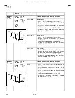
1. Input a stereo L signal (300Hz) from the TV Audio multiplex
signal generator to the antenna terminal. (NTSC)
2. Connect an oscilloscope to L OUT RCA pin of the AUDIO
OUT, and display one cycle portion of the 300Hz signal.
3. Change the connection of the oscilloscope to R OUT RCA pin
of the AUDIO OUT, and enlarge the voltage axis.
4. Select the No.7 LOW SEP. of the SOUND mode in SERVICE
MENU.
5. Confirm the initial setting value of the No.7 LOW SEP.
6. Adjust the No.7 LOW SEP. so that the stroke element of the
300Hz signal will become minimum.
7. Change the signal to 3kHz, and similarly adjust the “No.8 HI
SEP.
L-Channel
signal waveform
R-Channel
crosstalk portion
Minimum
1 cycle
[ AV-14F33
/PH
Only ]
No.
Setting item
Variable
range
Initial setting
value
2
IN LEVEL
000
~
063
020
3
FH MON
000 / 001
000
4
ST VCO
000
~
063
025
No.
Setting item
Variable
range
Initial setting
value
9
5FH MON.
000 / 001
000
10
SAP VCO.
000
~
063
026
6
FILTER
000
~
063
030
7
LOW SEP.
000
~
063
022
8
HI SEP.
000
~
063
063
All manuals and user guides at all-guides.com
all-guides.com

