background image

No. 52026

AV-14F3/AV-1435

AV-1435EE/AV-1435TEE

AV-14FMT3/AV-1438

AV-14FMG3/AV-14FMG3B

27

DEFLECTION CIRCUIT ADJUSTMENT

"

  There are 2 modes of adjustment (s etting value) ------ 

  50Hz mode and 

  60Hz mode ----- depending upon the kind of s ignals

(vertic al frequency 50Hz / 60Hz).

"

  When adjusted in mode 

 , mode 

  will be  automatically s et.

  The  setting (adjustmen t) usin g the  REMOTE CONTROL UNIT is  made on the basis  of the  initial setting values.
  The  setting values which  adjust  the screen to  the optimum condition can be different  from the initial settin g values.

Item

Measuring

instrument

Test point

Ad justment part

Description

Ad justment
of


V.HEIGHT

&
V.POSITION

Signal
generator

Remote
control unit

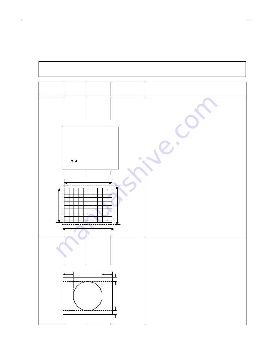
1. VER. POSITION
3. VER. 

HEIGHT

1. Input a circle pattern signal.
2. Enter the SERVICE MENU.
3. Select 

3. DEF.

 from SERVICE MENU.

4. Select 

1. VER. POSITION

 with the MENU 

/

 key.

5. Set the initial setting  value with the MENU  - / + key.
6. Adjust 

V

 and 

V’

 to be equal with the MENU - / + key as shown in

Fig.2.

7. Input a cross -hatch signal.
8. Select 

3. V. HEIGHT

 with  the MENU 

/

 key.

9. Set the initial setting  value with the MENU - / + key.
10. As shown in Fig.1, adjust 

VER. HEIGHT

 and mak e the vertical

screen size 

92%

 of the picture size with the MENU - / + keys of

remote control unit.

Ad justment

of


HOR.

POSITION

Signal
generator


Remote
control unit

2.HOR. POSITION

11. Input a circle pattern signal.
12. Select 

2. HOR POSITION

 with  the MENU 

/

 key.

13. Set the initial setting value of 

2. HOR. POSITION

 with  the

MENU - / + key.

14. Adjust 

2. HOR.  POSIT ION

 to  make 

H=H"

 as shown in Fig.2

with the MENU - / + key.

Scre en size

Picture size 1 00%

Scre en

size

92%

Picture
size
10 0%

Fig.1

H

H"

Fig.2

V

V'

DEF

- / + : OPERATE            DISP : EXIT

***

SUB MENU 3. DEF

     /       :SELECT

50Hz

1. VER. POSITION

PAL

Содержание AV-1435

Страница 1: ... 1435EE AV 1435TEE AV 14FMT3 AV 1438 AV 14FMG3 AV 14FMG3B AV 14FMG3 A CONTENTS SPECIFICATIONS 2 SAFETY PRECAUTIONS 3 FEATURES 4 FUNCTIONS 5 MAIN DIFFERENCE LIST 7 SPECIFIC SERVICE INSTRUCTIONS 8 SERVICE ADJUSTMENTS 15 PARTS LIST 33 OPERATING INSTRUCTIONS STANDARD CIRCUIT DIAGRAM 2 1 SERVICE MANUAL COLOUR TELEVISION BASIC CHASSIS CG RM C90 RM C364GY RM C364 ...

Страница 2: ... Hyper S21 S41 bands receivable VIF Carrier 38 0MHz Intermediate Frequency SIF Carrier 32 5MHz 5 5MHz 31 5MHz 6 5MHz 32 0MHz 6 0MHz 32 5MHz 5 5MHz 33 5MHz 4 5MHz 31 5MHz 6 5MHz 32 0MHz 6 0MHz Colour Sub Carrier Frequency PAL 4 43MHz SECAM 4 40625MHz 4 25MHz NTSC 3 58MHz 4 43MHz Power Input Rated Voltage AC110 240V 50 60Hz Power Consumption 68W Max 47W Avg Speaker 5cm 9 cm Oval type 2 Audio Output ...

Страница 3: ...must be the exact replacements or alternatives approved by the manufacturer of the complete product 7 Do not check high voltage by drawing an arc Use a high voltage meter or a high voltage probe with a VTVM Discharge the picture tube before attempting meter connection by connecting a clip lead to the ground frame and connecting the other end of the lead through a 10kΩ 2W resistor to the anode butt...

Страница 4: ...r IF V C DEF VSM PRESET PRESET SETUP TOUR By means of AUTO PROGRAM the TV stations can be selected automatically and the TV channels can also be rearranged automatically The TELETEXT SYSTEM has a built in FLOP system Only for AV 1435TEE AV 14FMT3 Built in ECO MODE ECONOMY ECOLOGY In accordance with the brightness in a room the brightness and of contrast of the picture can be adjusted automatically...

Страница 5: ...U buttons CHANNEL buttons VOLUME buttons AI ECO sensor REMOTE CONTROL sensor ON TIMER lamp POWER lamp MAIN POWER button A V INPUT terminal HEADPHONE jack 1 2 3 4 5 6 7 8 9 10 10 9 1 2 3 4 5 6 7 8 ANT Terminal VIDEO INPUT Terminal VIDEO OUTPUT Terminal AUDIO INPUT Terminal AUDIO OUT PUT Terminal 1 2 3 4 5 2 3 4 5 1 AV 1438 9 10 ...

Страница 6: ... 1435EE AV 1438 AV 14FMG3 AV 14FMG3 A RM C364 AV 14FMG3B ECO SENSOR key COLOUR SYSTEM key SOUND SYSTEM key DISPLAY key TV VIDEO key OFF TIMER key PICTURE MODE key CHANNEL SCAN key RETURN key CHANNEL key POWER key MUTING key TV TEXT key MENU key MENU key MENU key Number CH key key VOLUME key Teletext key 1 2 3 4 5 6 7 8 9 10 12 11 13 14 15 16 17 18 1 2 3 4 5 6 7 8 9 10 11 12 13 14 15 16 1 2 3 4 5 6...

Страница 7: ...e Model Name Inst Book Digest Manual Warranty Card Rating Label AV 14F3 LCT1188 001A H LCT1189 001A H LC20377 010B H AV 1435 LCT1190 001A H LC20377 001B H AV 1435EE LCT1195 001A H BT 54012 2 LC20377 009B H AV 1435TEE AV 14FMT3 LCT1174 001A H LCT1175 001A H LC20377 001B H AV 1438 LCT1188 001A H GG20024 001A H AV 14FMG3 LCT1196 001A H LCT1197 001A H LC20377 001B H AV 14FMG3B Av 14FMG3 A LC20413 002B...

Страница 8: ... removing the rear cover 1 As shown in figure remove the 2screws marked 2 Follow the same steps when removing the other hand speaker CHECKING THE MAIN PW BOARD 1 To check the back side of the PW Board 1 Pull out the MAIN PW Board Refer to REMOVING THE MAIN PW Board 2 Erect the PW Board vertically so that you can easily check the back side of the PW Board CAUTION When erecting the PW Board be caref...

Страница 9: ...No 52026 AV 14F3 AV 1435 AV 1435EE AV 1435TEE AV 14FMT3 AV 1438 AV 14FMG3 AV 14FMG3B 9 CRT SOCKET PWB FRONT CABI POWER CORD SPEAKER MAIN PWB E REAR COVER B A 2 1 4 PWB STOPPER D C 1 ...

Страница 10: ...s the DISPLAY key twice and return to the normal screen 5 Receive channel of setting Refer to the OPERATING INSTRUCTIONS and set the receive channels channels preset as described 6 User Setting Check the user setting value of Table 2 and if setting value is different set the correct value For setting refer to the OPERATING INSTRUCTIONS 7 Setting of SERVICE MENU Verify the setting items of the SERV...

Страница 11: ...T RATE 10 20 40 80 20 AMP TUNER NO VNR YES TEXT TABLE CYL ARA CYL VOLUM PW M POS Table 1 USER SETTING VALUES Setting item Setting value Setting item Setting value SUB POWER ON LANGUAGE ENGLISH CHANNEL POSITION 1 POSITION CHANNEL PRESET Refer to OPERATING INSTRUCTION VOLUME About 10 AI ECO SENSOR OFF TV VIDEO TV VNR OFF ON SCREEN DISPLAY POSITION INDICATION AUTO SHUTOFF OFF COLOUR SYSTEM PAL ON TIM...

Страница 12: ...T OFF BLUE 128 127 50 RED 2 DRIVE BLUE 128 127 0 3 BRIGHT 127 127 0 4 CONT 63 63 0 5 COLOUR 63 63 0 TV 0 0 AV 14F3 AV 1435 AV 1435EE 0 0 6 TINT VIDEO AV 1435TEE AV 14FMT3 AV 1438 AV 14FMG3 AV 14FMG3B AV 14FMG3 A 63 63 5 0 7 SECAM BL ADJ 31 31 0 TV 17 Fixed 8 SHARP Do Not Adj VIDEO 32 31 10 Fixed 3 DEFLECTION Initial setting value Setting item Variable range fv 50Hz MODE fv 60Hz MODE 1 VER POSITION...

Страница 13: ... 1 1 2 SHARP PEAK 0 0 0 0 3 ABL 1 1 1 1 4 GAMMA 0 0 0 0 TV 0 2 2 3 5 Y DELAY TIME VIDEO 0 2 0 2 6 BLACK EXP START 3 3 3 3 TV 1 1 0 0 7 C BPF VIDEO 1 1 1 1 8 CW SCP 0 0 0 0 9 VIF DET LEVEL 0 0 0 0 11 IF AGC MIN 0 0 0 0 12 VIF AGC 0 0 0 0 13 VIF PMOD 0 0 0 0 19 VNR 15 15 15 15 20 RGB LIM 1 1 1 1 21 RGB LIMIT LEVEL 2 2 2 2 23 TEXT H POSITION 3 3 3 3 24 READ DATA Sound System Do Not Adjust Setting ite...

Страница 14: ...the IC301 with a new one 3 While pressing MENU button and VOL button ON the FRONT CABINET simultaneously turn the POW ER ON When the POWER is turned ON the data is written in the micro computer immediately LOCATIONS OF FRONT PANEL BUTTONS AND LAM PS MENU buttons CHANNEL buttons MENU buttons VOLUME buttons MENU buttons AI ECO sensor REMOTE CONTROL sensor ON TIMER lamp POWER lamp MAIN POW ER button ...

Страница 15: ...s 5 Unless otherwise specified prepare the most suitable reception or input signal for adjustment 6 Never touch any adjustment parts which are not specified in the list for this adjustment VRs transforms condensers etc 7 Preparation for adjustment Unless otherwise specified in the adjustment instructions preset the following functions with the REMOTE CONTROL UNIT User mode position PICTURE MODE VS...

Страница 16: ...uld be able to select mode LANGUAGE and AUTO CH PRESET Should be OFF Key operation of the SERVICE MENU Enter to SERVICE MENU Press the DISPLAY key and the PICTURE MODE key of the REMOTE CONTROL UNIT simultaneously Then enter the SERVICE MENU mode as shown in Fig 1 Exit from SERVICE MENU When complete the adjustment work press the DISPLAY key to return to the SERVICE MENU And then press the DISPLAY...

Страница 17: ...he setting values of the setting items DISPLAYKey When this is pressed twice you will return to the SERVICE MENU 2 V C 3 DEF and 4 VSM PRESET 2 4Key Select one from 2 V C 3 DEF and 4 VSM PRESET MENU Key Select setting items MENU Key Adjust the values of the items DISPLAY Key When this is pressed return to the SERVICE MENU 6 SETUP TOUR Bypressing the 6 key you can change the ON or OFF should be OFF...

Страница 18: ...ISP EXIT DELAYPOINT UHF AGCTAKE OVER OPERATE DISP EXIT 6 SETUP TOUR ON OFF By pressing 6 key BRIGHT TINT COLOUR BRIGHT CONT SHARP OPERATE DISP EXIT SUB MENU 4 VSM PRESET SELECT DEF OPERATE DISP EXIT SUB MENU 3 DEF SELECT 50Hz 1 VER POSITION PAL V C PAL 1 CUTOFF OPERATE DISP EXIT R G B 50Hz SUB MENU 2 V C SELECT PRESET 1 C TRAP FIX OPERATE DISP EXIT 50Hz SUB MENU 5 PRESET SELECT B K PAL SERVICE MEN...

Страница 19: ...LOCATIONS S 1Pin TP 91 B1 2Pin NC 3Pin X ray2 4Pin X ray1 5Pin TP E HVT S1 HV U IC301 MEMORY IC IC702 IC701 F901 DEG TU001 FRONT TOP MAIN PWB CRT SOCKET PWB SOLDER SIDE TP 47G R E1 U T PW UPPER FOCUS LOWER SCREEN TP 47R G TP 47B TP E T CRT EARTH WIRE BRAIDED ASS Y IC821 Only for AV 1435TEE AV 14FMT3 ...

Страница 20: ...int Adjustment part Description Please use signal generator which is correct proof about the sending frequency Adjustment of VCO CW Signal generator Remote control unit 1 VCO 1 Input the PAL full colour bar 210 25MHz signal 2 Enter the SERVICE MENU 3 Select 1 IF from the SERVICE MENU 4 Press 1 key and select 1 VCO 5 Select VCO ADJUST with MENU key 6 Press MENU key until the colour of the character...

Страница 21: ... the SERVICE MENU 3 Select 1 IF from the SERVICE MENU 4 Select 2 DELAY POINT by pressing the 2 key on the remote control unit 5 Set the setting values of the setting items as shown bellow table 6 Then adjust the MENU or key until video noise disappears 7 Turn to other channels and make sure that there are no irregularities Setting Item Variable range Initial setting value MATSUSHITA QAU0287 001 NT...

Страница 22: ...9 of the remote control unit and adjust the other 2 colours which except the appeared colour to where the single horizontal line appears white 8 Turn the SCREEN VR to where the single horizontal line glows faintly 9 Press the 2 key to turn off the single horizontal line 10 Press the DISPLAY key twice to return to the normal screen Adjustment of WHITE BALANCE High light Signal generator Remote cont...

Страница 23: ... value with the MENU key 6 If the contrast is not the best with the initial set value make fine adjustment until you get the best contrast 5 COLOUR Method of adjustment without measuring instrument PAL COLOUR 1 Receive a PAL broadcast 2 Enter the SERVICE MENU 3 Select 2 V C from the SERVICE MENU 4 Select 5 COLOUR with the MENU key 5 Set the initial setting value for PAL COLOUR with the MENU key 6 ...

Страница 24: ... Voltage value between W and G SECAM COLOUR 1 Input a SECAM full field colour bar signal 75 white 2 Set the initial setting value of SECAM COLOUR with the MENU key 3 Adjust SECAM COLOUR to bring the value of A in the illustration to 10V W G Voltage value between W and G NTSC 3 58 COLOUR 1 Input a NTSC 3 58 full field colour bar signal 75 white 2 Set the initial setting value of NTSC 3 58 COLOUR wi...

Страница 25: ...rator Remote control unit NTSC 4 43 TINT When NTSC 3 58 is set NTSC 4 43 will be automatically set at the respective values 6 TINT Method of adjustment using measuring instrument NTSC 3 58 TINT 1 Input a NTSC 3 58 full field colour bar signal 75 white 2 Enter the SERVICE MENU 3 Select 2 V C from SERVICE MENU 4 Select 6 TINT with the MENU key 5 Set the initial setting value of NTSC 3 58 with the ME...

Страница 26: ... BL ADJUST with MENU key 5 Set the initial setting value with the MENU key 6 Switch the key colour OFF and key colour ON on the remote control and make sure that there is no colour on the black and white screen 7 If the black and white screen is not best with the initial setting value make fine adjustment until you get the best black and white screen 8 While watching the screen adjust the value to...

Страница 27: ... 2 Enter the SERVICE MENU 3 Select 3 DEF from SERVICE MENU 4 Select 1 VER POSITION with the MENU key 5 Set the initial setting value with the MENU key 6 Adjust V and V to be equal with the MENU key as shown in Fig 2 7 Input a cross hatch signal 8 Select 3 V HEIGHT with the MENU key 9 Set the initial setting value with the MENU key 10 As shown in Fig 1 adjust VER HEIGHT and make the vertical screen...

Страница 28: ... sure that the adjustment is properly done on the screen of 60Hz mode NOTE Adjust to make both 50Hz 60Hz are the same v size and fine straight line When adjust again adjust 50Hz mode first When adjust in 60Hz mode only 60Hz mode is adjust VSM PRESET SETTING Item Measuring instrument Test point Adjustment part Description Setting of VSM PRESET Remote control unit TINT COLOUR BRIGHT CONT SHARP 1 Ent...

Страница 29: ...that the GREEN RASTER will come into the center of the screen Fig 3 8 Move the deflection yoke forward and fix the position of the deflection yoke so that the whole screen will become green 9 Insert the wedge to the top side of the deflection yoke so that it will not move 10 Input a crosshatch signal 11 Verify that the screen is horizontal 12 Input red and blue raster signals and make sure that pu...

Страница 30: ...hite 4 Repeat 2 and 3 above and make best convergence DYNAMIC CONVERGENCE ADJUSTMENT 1 Move the deflection yoke up and down and overlap the lines in the periphery Fig 2 2 Move the deflection yoke left to right and overlap the lines in the periphery Fig 3 3 Repeat 1 and 2 above and make best convergence After adjustment fix the wedge at the original position Fasten the retainer screw of the deflect...

Страница 31: ... at each end 2 Shift with tweezers and remove the chip part Transistors diodes variable resistors etc 1 Apply extra solder to each lead 2 As shown in the figure push the part with tweezers and alternately melt the solder at each lead Shift and remove the chip part Note After removing the part remove remaining solder from the pattern 2 How to install Chip parts Resistors capacitors etc 1 Apply sold...

Страница 32: ...No 52026 AV 14F3 AV 1435 AV 1435EE AV 1435TEE AV 14FMT3 AV 1438 AV 14FMG3 AV 14FMG3B 32 ...

Отзывы: