10
www.juwent.com.pl
9. ELECTRICAL INSTALLATION
The electric installation and the connection of power to the unit must be executed according to the
relevant requirements of the standards and construction regulations..
The electric connections of the unit may be executed only by an authorized electrician
who got acquainted with the instruction manual.
Before the connection it is necessary to make sure whether the voltage value and power system
frequency are compliant with the data specified on the rating plates of the units. In case of
noncompliance the unit should not be connected.
The units are equipped with single (1~230 V/50 Hz) fans with internal thermal contacts TK (brought
to the terminal box or stuck in the motor circuit permanently). The electric connection of the fan
should be executed taking a service switch (WS) and overload and short-circuit protection devices in
the supply and control box into consideration.
The lack of required motor safety devices and non-connection of thermal contact TK to
the control circuit cause the loss of warranty
The lead powering the fan should be inserted to the terminal box and fastened to the protective net
or fan supports by means of clamp bands. The thermal contact of the fan should be connected to
the circuit that controls the power supply of the fan.
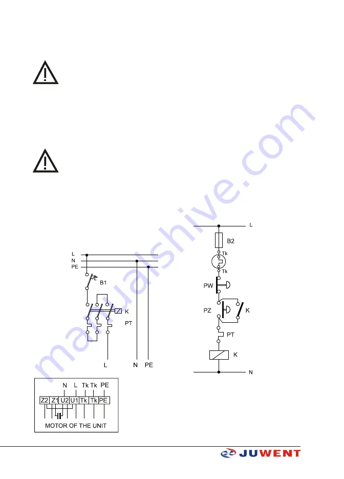
The electric connection of the motor must be compliant with the electric diagrams located on the
terminal box. The exemplary connection and control diagram of the units are presented in the
picture 1.
MOTOR LEAD DESIGNA-
TION:
U1 - brown
U2 - blue
Z1 - black
Z2 - orange
Tk - white
DIAGRAM DESIGNATIONS:
PT – Overcurrent protection of the motor
K – Contactor
PZ – Switch-on control button
PW – Switch-off control button
B1,B2 – Fuses
PE – Protective terminal
Tk – Thermal protection
Fig. 1. TROPIC unit connection and control diagram


