JA95-043
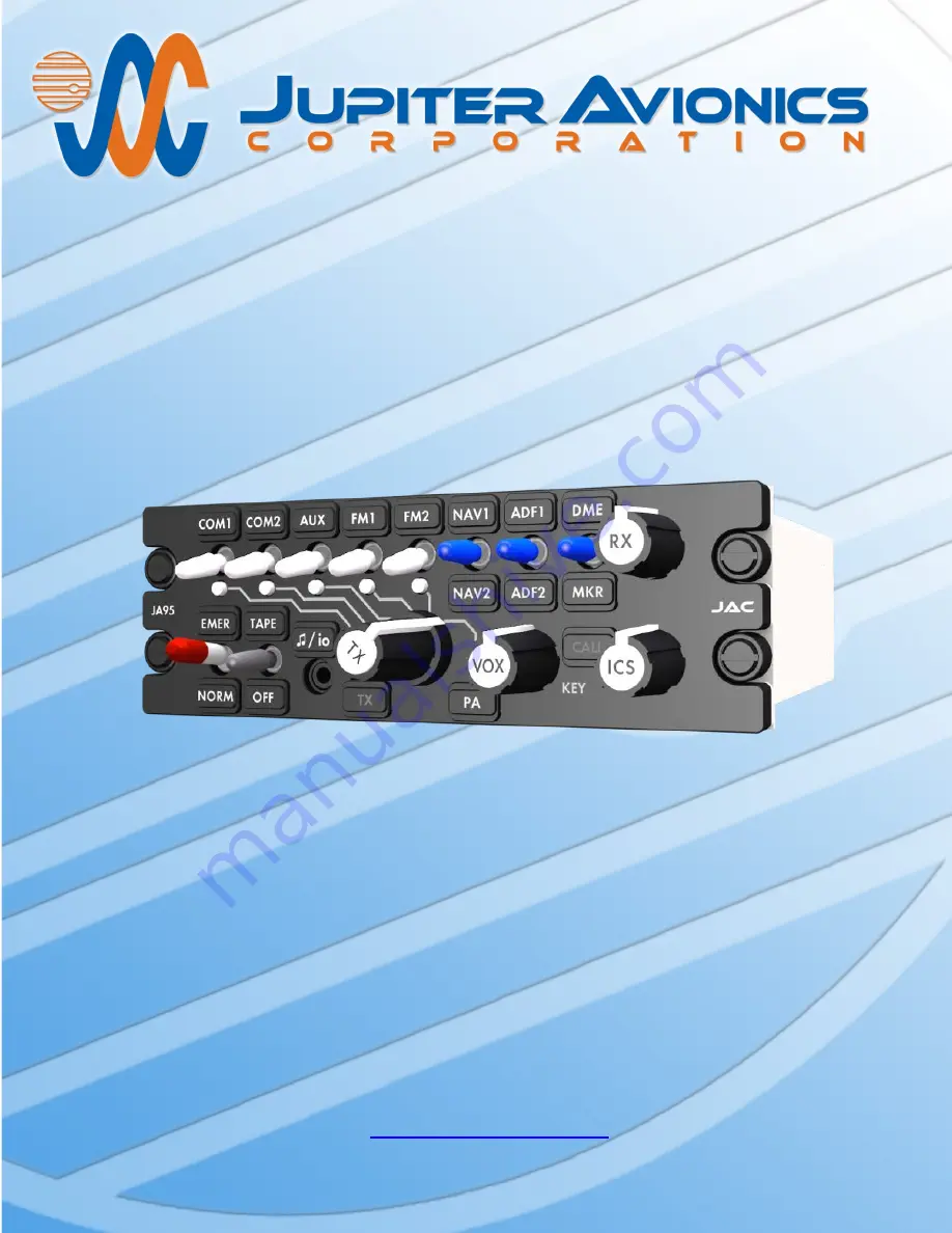
Audio Controller - AMS43 Compatible
Installation and Operating Manual
Rev. B
Jupiter Avionics Corporation
1959 Kirschner Road
Kelowna BC
Canada V1Y 4N7
Tel: 778-478-2232
Toll-Free: 855-478-2232
www.jupiteravionics.com
Страница 1: ...udio Controller AMS43 Compatible Installation and Operating Manual Rev B Jupiter Avionics Corporation 1959 Kirschner Road Kelowna BC Canada V1Y 4N7 Tel 778 478 2232 Toll Free 855 478 2232 www jupiteravionics com ...
Страница 2: ...bution of this manual is strictly prohibited Except as described above no part of this manual may be reproduced copied transmitted disseminated downloaded or stored in any storage medium for any purpose without the express prior written consent of JAC RECORD OF REVISIONS Revision Rev Date Description ECR A Jul 2015 Initial release Serial number 1001 and higher 2815 B May 2017 Music Input Levels an...
Страница 3: ...g and Wiring 6 2 4 3 Mechanical Installation 7 2 4 4 In Line PTT Cordsets 7 2 4 5 Legend Replacement 7 2 4 6 Post Installation Checks 7 2 5 Adjustments and Configuration using ProCS 8 2 5 1 Configuration Cabling Requirements 8 2 5 2 ProCS Setup 8 2 5 3 Configurable Settings 8 2 5 4 Other Configuration Features 14 2 6 Installation Kit 14 2 6 1 Recommended Crimp tools 15 2 7 Installation Drawings 15...
Страница 4: ...TT Operation 20 3 3 5 VOX Operation 20 3 3 6 ICS Operation 20 3 3 7 Music Operation 20 3 4 Emergency Operation Mode 20 3 4 1 Auto Emergency Mode 20 3 4 2 Selected Emergency Mode 20 Appendix A Installation Drawings A1 A1 Introduction A1 A2 Installation Drawings A1 Appendix B Certification Documents B1 B1 Airworthiness Approval B2 B2 Instructions for Continued Airworthiness B2 B3 Environmental Quali...
Страница 5: ...ny of the JA95 043 input and output levels are adjustable several audio paths are selectable and alert audio analog waveforms can be loaded using the configuration program ProCS Product Configuration Software to write configuration commands via the JA99 001 configuration cable to the front panel music configuration connector The audio waveforms are stored in non volatile devices The alert audio fe...
Страница 6: ... AUDIO 2 HI LO 1 Audio signal FRONT PANEL MUSIC 2 Audio signal LIGHTS INPUT 1 Analog control signal MIC 7 Audio signal Pilot Copilot Rear Hand and PAX 1 4 MIC HI LO MODE SELECT CONFIG AUDIO 1 Multi format signal PILOT COPILOT PHONES HI LO 2 Active low discrete PILOT and COPILOT TX PTT 2 Active low discrete POWER INPUT 1 14 to 28 Vdc power supply REAR HAND TX PTT 1 Active low discrete RX AUDIO 11 A...
Страница 7: ...ms 10 CONFIG AUDIO input level 400 mVrms 10 Rated Output Level Phone rated output 7 75 Vrms 10 Pilot Phone rated output in emergency mode or with power input 6 Vdc 2 20 Vrms 10 Phone rated output power with MUSIC input 3 88 Vrms 10 Microphone rated output 250 mVrms 10 Intercom Tie Line type 1 rated output 340 mVrms 10 Intercom Tie Line type 2 rated output 1 2 Vrms 10 Audio Frequency Response Audio...
Страница 8: ...gh a 100 Ohm Ω 20 resistor 1 4 1 3 Discrete Signals Active low control input active signal level 3 Vdc Active low control input inactive signal level 10 Vdc Active low control input current 10 mAdc Active low control output active output 2 Vdc Active low control output active current 1 Adc ALERT ENABLE signal active signal level 9 Vdc ALERT ENABLE signal when active sinks 10 mAdc ALERT ENABLE sign...
Страница 9: ...listed below Environmental categories for which TSO compliance has been demonstrated are listed in the Environmental Qualification Form in Appendix B of this manual Temperature Operating 45 to 70 C Ground Survival 55 to 85 C Altitude 50 000 ft Humidity Cat A 48 hours Shock Crash Safety 6 g 20 g for 11 ms 1 4 4 Flammability of Materials The JA95 043 complies with the requirements of RTCA DO 160G Se...
Страница 10: ...DEALER If the on line warranty card is not completed the product will be warranted from the date of manufacture Contact JAC for return authorization and for any questions regarding this warranty and how it applies to your unit s JAC is the final arbiter concerning warranty issues 2 4 Installation Procedures WARNING Loud noise can cause hearing damage Set the headset volume to minimum before conduc...
Страница 11: ...cument in Appendix A of this manual 2 4 6 Post Installation Checks 2 4 6 1 Voltage Resistance checks Do not attach this unit until the following conditions are met a Check P1 pin 19 for lighting buss voltage b Check P2 pin 16 for 28 Vdc Alert Power relative to ground c Check P2 pin 17 for 28 Vdc relative to ground d Check P2 pin 34 for continuity to ground less than 0 5 Ω e Check P2 pins 7 thru 10...
Страница 12: ...and for installation of ProCS on your computer refer to the ProCS manual on the Jupiter Avionics website www jupiteravionics com productsoftware 2 5 1 Configuration Cabling Requirements To configure the JA95 043 it is necessary to load the Product Configuration Software ProCS onto a Windows based computer as described in the ProCS manual The cables required to configure the JA95 043 are not includ...
Страница 13: ...specify the text for each legend Note If the name of a front panel switch is changed using this software the change will be incorporated in every other section that refers to that switch name including the connector maps to give truly customized installation diagrams 2 5 3 2 Radios The Radios window is used to define the radios for the transceivers and receivers ...
Страница 14: ...B Page 10 2 5 3 3 Receive Levels The receive and direct audio input level of each of the eleven RX and the DIRECT AUDIO inputs can be adjusted from 1 to 10 Vrms Default 7 75 Vrms The Receive Audio Detector threshold can be adjusted from 36 to 12 dB of rated input level Default 24 dB ...
Страница 15: ...peration Default not checked see section 3 3 4 2 5 3 5 Sidetone Levels 2 5 3 6 Connector Pin Configuration The level of each of the six Transceiver MIC output signals can be adjusted from 0 01 to 1 Vrms Default 250 mVrms The Receive Sidetone Level can be adjusted from 0 to 12 dB of the rated phone Level Default 6 dB The level of the PA Artificial Sidetone can be adjusted from 0 to 30 dB of the rat...
Страница 16: ...e signals to be customized with other recordings during the configuration process The default Alert signals loaded into the unit at the factory are JA95 043 Wav File Sine 300Hz 10 sec Rev A WAV JA95 043 Wav File Sine 1000Hz 10 sec Rev A WAV JA95 043 Wav File Sine 3000Hz 10 sec Rev A WAV Saving new Audio Files If a new audio file is selected it may be played using the arrow to the right of the Mess...
Страница 17: ...usic Audio is always enabled 2 5 3 9 Tape Levels The music output level of the four Tape Music input signals to the Phones audio can be adjusted from 40 to 0 dB of rated phone level Default 0 dB The attenuation level during muting of the music signal can be adjusted from 0 to 40 dB Default 40 dB The Music Input Levels cannot be adjusted The default level is 0 40 Vrms 2 5 3 10 ICS Tie Line The rate...
Страница 18: ...mments pane of the JA95 043 Product Information Window for future reference 2 6 Installation Kit The kit required to install this unit is not included with the unit The installation kit Part INST 95043 consists of the following Quantity Description JAC Part 1 37 socket Zinc plated Crimp Socket Housing CON 3460 0137 1 50 socket Zinc plated Crimp Socket Housing CON 3460 0150 1 37 pin clamshell Plast...
Страница 19: ...gs The drawings and documents required for Installation can be found in Appendix A of this manual 2 7 1 Generation of Custom Drawings The interconnects and connector maps in Appendix A of this manual are generic drawings based on the standard version of the JA95 043 However if a unit has been configured using JAC s ProCS software to change switch legends or lighting voltages the software can be us...
Страница 20: ... the purpose of this manual the controls will be referred to by the default legend and annunciator names as shown below 1 Transceiver Receive Switches and Associated Legends 2 Receiver Switches and Associated Legends 3 Receive Volume Control 4 Mode Switch 5 Tape Off Switch 6 Music Configuration Input Connector and Legend 7 Transmit Annunciator Deadfront 8 Transmit Selector 9 PA Legend 10 VOX Thres...
Страница 21: ... volume of the receive audio from minimum when fully counterclockwise ccw to maximum when fully clockwise cw Individual radio volume controls should be set to a nominal level and then adjusted for changing flight conditions using this control 4 Mode Switch This is a red two position locking toggle switch When set to the up position the unit is Emergency mode and when set to the down position the u...
Страница 22: ...stem PA Each of the transmit selector positions is linked by a white line to the corresponding transmit select annunciator transceiver switch and legend The appropriate annunciator will light green to show which transceiver is selected for transmit PA in this example 9 PA Legend This is a customizable legend to mark the PA position for the transmit selector The interchangeability allows an appropr...
Страница 23: ... to the unit 3 3 1 Panel Lighting The legends and annunciators will be illuminated when appropriate and dim through the aircraft lighting buss 3 3 2 Receiving When the JA95 043 receives an incoming transmission on a transceiver or receiver that has been selected either by the white transceiver receive switches 1 or the transmit selector 8 the incoming audio will be directed to the user s phones Th...
Страница 24: ...ICS Receive Direct or Alert Audio or if the unit is transmitting When the incoming audio has ended the music will gradually return to the previous level Music either from the rear tape input or from the front panel music input or both will also be muted if the TAPE OFF switch is in the OFF position Placing the switch in the TAPE position will allow the music to be unmuted 3 4 Emergency Operation M...
Страница 25: ...A95 043 Audio Controller AMS43 Compatible are in this Appendix as listed below Note A fully customized set of Connector Maps and Interconnects can be created using the ProCS software Refer to the ProCS manual for further information A2 Installation Drawings DOCUMENT Rev JA95 043 Connector Map A JA95 043 Interconnect A JA95 043 Mechanical Installation A Reference Documents TOL CUST EXTR Legend Repl...
Страница 26: ...M 1 RX LO FM 2 RX LO NAV 1 RX LO NAV 2 RX LO ADF 1 RX LO ADF 2 RX LO DME RX LO MKR RX LO DIRECT AUDIO 1 LO TAPE LEFT LO TAPE RIGHT LO ICS TIE LO COPILOT PHN LO PILOT PHN LO P1 37 PIN FEMALE DMIN MATING CONNECTOR COM RX NAV RX RECEIVE CONNECTOR VIEW IS FROM REAR OF MATING CONNECTOR JUPITER AVIONICS TEMPLATE AUTOCAD PORTRAIT SIZEA REV B DWT TITLE APPROVED PREPARED CHECKED L00N3 NCAGE CODE PART NO SH...
Страница 27: ...HN HI PAX 4 PHN LO COM 1 PTT AUX PTT FM 1 PTT FM 2 PTT REAR HAND PTT PILOT TX PTT PILOT ICS PTT COPILOT TX PTT COPILOT ICS PTT ALERT 1 KEY ALERT 2 KEY ICS CALL ALERT 3 KEY PA MIC HI PA MIC LO ALERT ENABLE POWER INPUT POWER GROUND P2 50 PIN FEMALE DMIN MATING CONNECTOR PTT OUT PTT IN MIC OUT MIC IN PAX PHN OUT VIEW IS FROM REAR OF MATING CONNECTOR PAX 3 PHN HI PAX 3 PHN LO ALERT IN TRANSMIT CONNECT...
Страница 28: ... DATA TO JA95 CONFIG DATA FROM JA95 GROUND MODE SELECT CONFIG AUDIO FRONT PANEL MUSIC LEFT FRONT PANEL MUSIC RIGHT GROUND FRONT PANEL MUSIC CONFIGURATION CONNECTOR 3 POLE MALE 3 5MM STEREO JUPITER AVIONICS TEMPLATE AUTOCAD PORTRAIT SIZEA REV B DWT TITLE APPROVED PREPARED CHECKED L00N3 NCAGE CODE PART NO SHEET DOC NO CONFIDENTIAL PROPRIETARY TO JUPITER AVIONICS CORP Audio Controller P3 Connector Ma...
Страница 29: ...E THE OPTIONS SECTION OF THIS DRAWING FOR ALTERNATE INTERCONNECT WIRING ONLY 28 VDC OR 14 VDC OR 5 VDC LIGHTS INPUT VOLTAGE MAY BE APPLIED AT ONE TIME THE FRONT PANEL MUSIC INPUT SHALL NOT BE CONNECTED TO ANY OTHER AUDIO INPUT THE DIRECT AUDIO 2 SHALL NOT BE WIRED IN PARALLEL WITH ANY OTHER AUDIO INPUT THE DIRECT AUDIO 2 INPUT IS BEST SUITED FOR AUDIO SIGNALS THAT ARE TO BE ROUTED TO THE PILOT PHO...
Страница 30: ... TAPE LEFT LO RX LO TAPE LEFT 14 33 TAPE RIGHT HI TAPE RIGHT LO RX LO TAPE RIGHT 15 34 ICS TIE HI ICS TIE LO HI LO ICS TIE EXPANSION 16 35 COPILOT PHN HI COPILOT PHN LO PHN LO COPILOT HEADSET JACK 17 36 PILOT PHN HI PILOT PHN LO PHN LO PILOT HEADSET JACK 18 37 LIGHTS INPUT 28 VDC LIGHTS 19 JA95 043 J1 P1 37 PIN FEMALE DMIN MATING CONNECTOR 2 3 2 4 DIRECT AUDIO 2 HI DIRECT AUDIO 2 LO HI LO DIRECT A...
Страница 31: ...O 30 47 MIC LO PAX 2 HEADSET JACK PHN LO PAX 2 MIC HI PAX 2 MIC LO 27 44 PAX 2 PHN HI PAX 2 PHN LO 31 48 MIC LO PAX 3 HEADSET JACK PHN LO PAX 3 MIC HI PAX 3 MIC LO 28 45 PAX 3 PHN HI PAX 3 PHN LO 32 49 MIC LO PAX 4 HEADSET JACK PHN LO PAX 4 MIC HI PAX 4 MIC LO 29 46 PAX 4 PHN HI PAX 4 PHN LO 33 50 PA MIC HI PA MIC LO MIC LO PA SYSTEM 14 15 ALERT 1 KEY 11 ALERT 1 KEY ALERT 2 KEY 12 ALERT 2 KEY ALER...
Страница 32: ...L MUSIC LEFT FRONT PANEL MUSIC RIGHT GROUND 3RD RING TIP 1ST RING 2ND RING J3 CONFIG DATA TO JA95 CONFIG DATA FROM JA95 GROUND MODE SELECT CONFIG AUDIO CONFIG DATA TO JA95 CONFIG DATA FROM JA95 GROUND 3RD RING TIP 1ST RING 2ND RING MODE SELECT CONFIG AUDIO 6 JA95 043 FRONT PANEL MUSIC CONFIGURATION INPUT JUPITER AVIONICS TEMPLATE AUTOCAD PORTRAIT SIZEA REV B DWT TITLE APPROVED PREPARED CHECKED L00...
Страница 33: ...3 J4 THREADED STUD 4 40 0 25 in OPTION CHASSIS GROUND 22 AWG JUPITER AVIONICS TEMPLATE AUTOCAD PORTRAIT SIZEA REV B DWT TITLE APPROVED PREPARED CHECKED L00N3 NCAGE CODE PART NO SHEET DOC NO Audio Controller AMS43 Compatible Interconnect Options JA95 043 5 6 JA95 043 Interconnect Rev C dwg TAT JAC AH 11 02 15 JAC KDV 11 02 15 ...
Страница 34: ...LOT PHN LO 17 36 J1 P1 37 PIN FEMALE DMIN MATING CONNECTOR COPILOT MIC HI COPILOT MIC LO 25 42 COPILOT TX PTT 8 HI LO KEY COPILOT MIC JACK COPILOT TX KEY PRIMARY JACK J2 P2 50 PIN FEMALE DMIN MATING CONNECTOR JA95 043 3 REAR USER PHN HI REAR USER PHN LO COPILOT PHN HI COPILOT PHN LO 17 36 J1 P1 37 PIN FEMALE DMIN MATING CONNECTOR COPILOT MIC HI COPILOT MIC LO 25 42 COPILOT TX PTT 8 REAR USER MIC H...
Страница 35: ...VIONICS TEMPLATE SOLIDWORKS PORTRAIT SIZEA REVB DRWDOT DOC NO L00N3 PART NO TITLE 0 5 DEG Audio Controller AMS43 Compatible JA95 043 Mechanical Installation Rev A SLDDRW UNLESS OTHERWISE SPECIFIED DIMENSIONS ARE IN INCHES ANGLES ARE IN DEGREES TOLERANCES 1 DEC PLACE 0 1 2 DEC PLACE 0 01 3 DEC PLACE 0 005 ANGLES CONFIDENTIAL PROPRIETARY DRAWING NOT TO SCALE 0 30in MAX 7 6mm MAX 139 2mm MAX 5 48in M...
Страница 36: ...only minimal changes The internal circuitry ensures that although the legends are individually illuminated the illumination is consistent and uniform throughout all legends and never needs to be balanced This means that if it is a requirement to change the labelling due to damage or for a different project there is no need for costly and time consuming illumination checks Caution Take care not to ...
Страница 37: ...Rev B Page B1 JA95 043 Audio Controller AMS43 Compatible Installation and Operating Manual Appendix B Certification Documents ...
Страница 38: ...e net electrical load is unchanged Aircraft equipment list weights and balance amended Compass compensation checked and found to conform to applicable regulations B2 Instructions for Continued Airworthiness Maintenance of the JA95 043 Audio Controller AMS43 Compatible is on condition only Refer to the JA95 043 Maintenance Manual Periodic maintenance of the JA95 043 is not required The following sa...
Страница 39: ... this manual the JA95 043 Installation and Operating Manual If the unit is removed and reinstalled a functional check of the equipment should be conducted 8 Diagrams Refer to Appendix A of this manual the JA95 043 Installation and Operating Manual for installation drawings and interconnect examples 9 Special Inspection Requirements N A 10 Application of Protective Treatments N A 11 Data Relative t...
Страница 40: ...ory A1 8 000 to 50 000 ft Overpressure 4 6 3 Equipment tested to Category A1 15 000 ft Temperature Variation 5 0 Equipment tested to Category B 5 C min Humidity 6 0 Equipment tested to Category A 48 hours Operational Shock and Crash Safety Operational Shock Crash Safety impulse Crash Safety sustained 7 0 Equipment tested to Category B 6 g for 11 ms Equipment tested to Category B 20 g for 11 ms Equ...
Страница 41: ...ormed Salt Fog Test 14 0 Equipment identified as Category X no test performed Magnetic Effect 15 0 Equipment tested to Category Z 0 D 0 3 m Power Input DC Equipment DC Current Ripple DC Inrush 16 0 Equipment tested to Category Z 28 Vdc equipment B 14 Vdc and 28 Vdc equipment X no test performed X no test performed Voltage Spike 17 0 Equipment tested to Category A 600Vp 10 us Audio Frequency Suscep...
Страница 42: ...S 1 This product is a derivative of the JA95 001 All tests were performed on the JA95 001 A similarity analysis between the two products is detailed in the Jupiter Avionics Corp document JA95 043 CAN TSO Design Change Assessment Rev A 2 Test information can be found in the Jupiter Avionics Corp document JA95 001 Test Report Qualification Final Rev B 3 Testing of Radio Frequency Susceptibility Radi...