background image

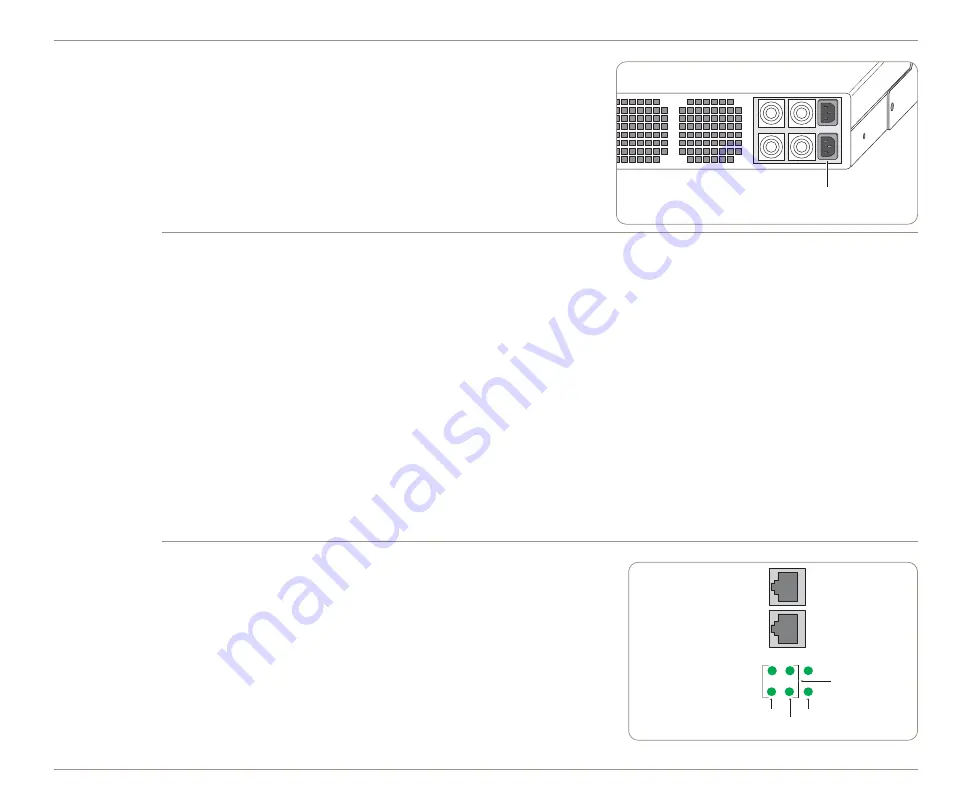
Connect the power.

Connect a power cable to each of the power supplies on the back of the

chassis, and connect the other end of the power cables to your local AC

power source. If one power supply stops functioning, the other power

supply can continue providing full power indefinitely.  A failed power

supply can be removed and replaced while the device is running.

NOTE:

The power usage is 300 Watts Max or 1025 BTU/hr.  When you

want to disconnect power from the device, unplug BOTH power cables.   

Configure the Network Settings.

Connect an ANSI compatible terminal to the console port, and use a terminal emulation program (e.g., HyperTerminal) 

to log in to the CLI. Note the following serial port settings:

Baud Rate: 

9600

, Data Bits: 

8

, Parity: 

NONE

, Stop Bits: 

1

,

Flow Control: 

NONE

, Smooth-Scroll: 

DISABLED

Start the terminal emulation program, and choose to connect via the serial port.

At the User name and Password prompts, type 

admin

for the user name and 

peribit

for the password.

Type an IP address, and press 

Enter

. Next, type the subnet mask for the network, and press 

Enter

. Finally, type the  

IP address of the default gateway for this device, and press 

Enter

.

Type “save-config” and type “y” to confirm. You can safely bypass the other configuration questions at this time.

NOTE: 

By default, the interfaces are set to auto-negotiate.  However, depending on the interface settings of the switch and

router (auto-negotiate or 1000/Full) it is recommended that you set the interface speed manually. The Local port setting

should match the interface settings of the switch, and the Remote port setting should match the interface settings of the

router. It is also recommended that the Local and Remote interface settings be the same.

Check the LEDs below the Local and Remote interfaces.

5

The BaseT Ethernet version has two rows of three LEDs: 

The Link/Activity LEDs indicate connectivity.

The 100 and 1000 LEDs indicate the interface speed in Mbps.

If the 100 and 1000 LEDs are off, the interface speed is 10 Mbps. 

If all 100 and 1000 LEDs are on, the device is in passthrough mode.

5

The fiber-optic version has one LED for each interface to indicate 

1000 Mbps.

After checking the LEDs, verify connectivity across the device again 

(as described in Step 3).

AC power

inputs

Remote port LEDs

Local port LEDs

Link/Activity

100

1000

Remote port

Local port

Passthrough

mode

WX 100

QUICK START

Содержание WX 100

Страница 1: ...ic connectors in a high availability HA environment Inspect the package contents Refer to the package contents document enclosed with the product Ensure sufficient AC power is available Supply circuits should be protected by a maximum 20A circuit breaker Ensure a minimum of 6 inches clearance in the front and back of the chassis Reserve sufficient rack space to connect client WX devices to the WX ...

Страница 2: ...over cable to allow traffic to pass through during a reboot or system failure all other WX platforms use a straight through cable Always test connectivity with the power off see the next step IMPORTANT Fiber Optic connectors do not support the switch to wire feature Therefore it is strongly recommended that you install a WX 100 with fiber optic connectors in a high availability HA environment Veri...

Страница 3: ...the IP address of the default gateway for this device and press Enter Type save config and type y to confirm You can safely bypass the other configuration questions at this time NOTE By default the interfaces are set to auto negotiate However depending on the interface settings of the switch and router auto negotiate or 1000 Full it is recommended that you set the interface speed manually The Loca...

Страница 4: ...Network Password dialog box type admin for the user name and peribit for the password NOTE This is a factory configured password for the device You will be asked to change the default password during the Quick Setup Select an Operating Mode A device can run in Active mode or Profile Mode Active Mode Active operation where the device reduces data accelerates TCP applications and manages bandwidth P...

Страница 5: ...er devices until you enable reduction tunnel formation in the Endpoints page of the Web console Click Next to continue Set the Time If your network uses an NTP server for device time settings enter the IP address of the NTP server Otherwise enter the current time date and local time zone for the device If applicable select the Daylight Savings checkbox Click Next to continue Specify Feature and To...

Страница 6: ...ermanent license key through the Online License Service The License Key server is accessible by clicking Online Service or by calling Support at 1 888 314 JTAC or 408 745 9500 Enter the permanent license key in the License key field Click Next to continue Change Administrator password Enter a new Administrator password in the New password and Verify new password fields and then click Finish NOTE I...

Отзывы: