When handling fiber-optic transceivers and fiber-optic cable, observe the following
precautions:
•
Do not leave a fiber-optic transceiver uncovered except when inserting or removing
cable. The safety cap keeps the port clean and prevents accidental exposure to laser
light.
•
Do not bend fiber-optic cable beyond its minimum bend radius. An arc smaller than
a few inches in diameter can damage the cable and cause problems that are difficult
to diagnose.
•
Do not let fiber-optic cable hang free from the connector. Do not allow fastened loops
of cable to dangle, which stresses the cable at the fastening point.
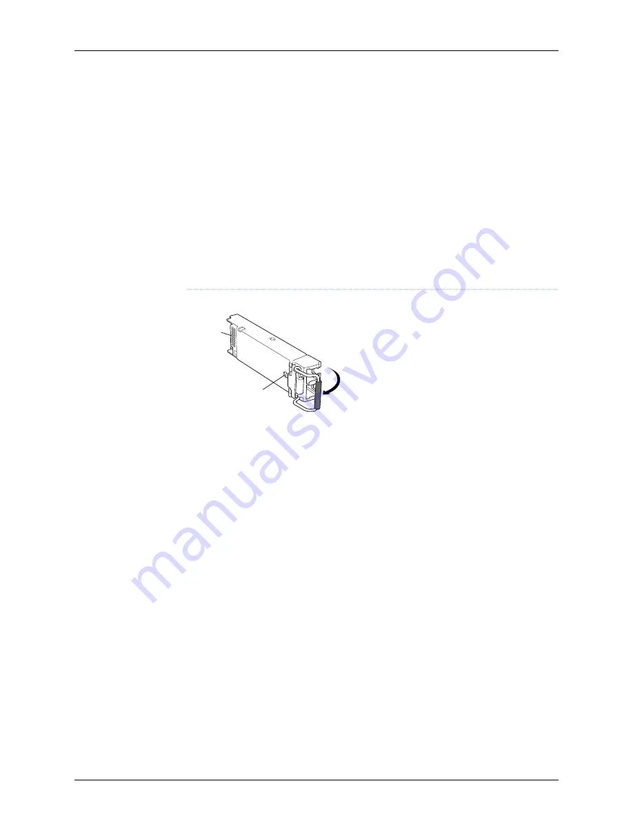
Figure 9: Small Form-Factor Pluggable (SFP)
g001855
Connector
Locking pin
To install an SFP transceiver in the LN1000–V RTM:
1.
Attach an electrostatic discharge (ESD) grounding strap to your bare wrist, and
connect the strap to one of the ESD points on the chassis.
2.
Verify that a rubber safety cap covers the SFP transceiver, installing one if necessary.
3.
Orient the SFP over the port in the RTM so that the connector end will enter the slot
first and the SFP connector faces the appropriate direction:
4.
Slide the SFP into the slot. If there is resistance, remove the SFP and flip it so that
the connector faces the other direction.
5.
Remove the rubber safety cap from the transceiver and the end of the cable, and
insert the cable into the transceiver.
6.
Arrange the cable in the cable management system to prevent the cable from
dislodging or developing stress points. Secure the cable so that it is not supporting
its own weight as it hangs to the floor. Place excess cable out of the way in a neatly
coiled loop in the cable management system. Placing fasteners on the loop helps
to maintain its shape.
7.
Verify that the SFP is installed by entering the CLI
show chassis hardware detail
command. Output will display as follows:
root@spencer# run show chassis hardware
Hardware inventory:
Item
Version Part number Serial number
Description
Chassis
BF1809AG0055
LN1000-v
31
Copyright © 2010, Juniper Networks, Inc.
Chapter 10: Installing the LN1000–V Rear Transition Module
Содержание LN1000-V
Страница 1: ...LN1000 V Mobile Secure Router Hardware Guide Published 2010 07 20 Copyright 2010 Juniper Networks Inc...
Страница 6: ...Copyright 2010 Juniper Networks Inc vi...
Страница 10: ...Copyright 2010 Juniper Networks Inc x LN1000 V Mobile Secure Router Hardware Guide...
Страница 12: ...Copyright 2010 Juniper Networks Inc xii LN1000 V Mobile Secure Router Hardware Guide...
Страница 18: ...Copyright 2010 Juniper Networks Inc xviii LN1000 V Mobile Secure Router Hardware Guide...
Страница 20: ...Copyright 2010 Juniper Networks Inc 2 LN1000 V Mobile Secure Router Hardware Guide...
Страница 34: ...Copyright 2010 Juniper Networks Inc 16 LN1000 V Mobile Secure Router Hardware Guide...
Страница 36: ...Copyright 2010 Juniper Networks Inc 18 LN1000 V Mobile Secure Router Hardware Guide...
Страница 40: ...Copyright 2010 Juniper Networks Inc 22 LN1000 V Mobile Secure Router Hardware Guide...
Страница 46: ...Copyright 2010 Juniper Networks Inc 28 LN1000 V Mobile Secure Router Hardware Guide...
Страница 52: ...Copyright 2010 Juniper Networks Inc 34 LN1000 V Mobile Secure Router Hardware Guide...
Страница 53: ...PART 3 Index Index on page 37 35 Copyright 2010 Juniper Networks Inc...
Страница 54: ...Copyright 2010 Juniper Networks Inc 36 LN1000 V Mobile Secure Router Hardware Guide...


