background image

6.

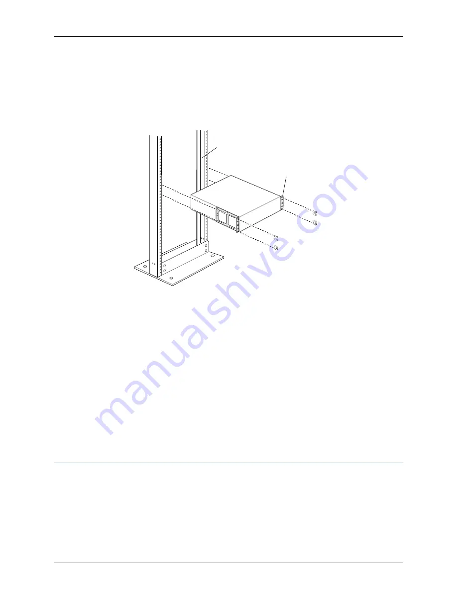
Have one person grasp both sides of the switch, lift the switch, and position it in the
rack, aligning the mounting bracket holes with the threaded holes in the rack or cabinet
rail. Align the bottom hole in both the mounting brackets with a hole in each rack rail,
making sure the chassis is level. See

Figure 31 on page 116

.

Figure 31: Mounting the Switch on Two Posts in a Rack

Mounting rack

Mounting bracket

g020819

7.

Have a second person secure the switch to the rack by using the appropriate screws.
Tighten the screws.

8.

Ensure that the switch chassis is level by verifying that all screws on one side of the
rack are aligned with the screws on the other side.

9.

We recommend that you insert dust covers in any unused ports.

Related

Documentation

Connecting Earth Ground to an EX Series Switch on page 137

Connecting AC Power to an EX4500 Switch on page 143

Connecting DC Power to an EX4500 Switch on page 145

Connecting and Configuring an EX Series Switch (CLI Procedure) on page 161

Connecting and Configuring an EX Series Switch (J-Web Procedure) on page 164

Rack-Mounting and Cabinet-Mounting Warnings on page 236

Mounting an EX4500 Switch on Four Posts in a Rack or Cabinet

You can mount an EX4500 switch on four posts of a 19-in. rack or cabinet by using the
separately orderable four-post rack-mount kit. (The remainder of this topic uses “rack”
to mean “rack or cabinet.”)

Copyright © 2015, Juniper Networks, Inc.

116

Complete Hardware Guide for EX4500 Ethernet Switches

Содержание EX4500-40F-BF

Страница 1: ...Complete Hardware Guide for EX4500 Ethernet Switches Modified 2015 06 23 Revision 13 Copyright 2015 Juniper Networks Inc ...

Страница 2: ...products are Year 2000 compliant Junos OS has no known time related limitations through the year 2038 However the NTP application is known to have some difficulty in the year 2036 SOFTWARE LICENSE The terms and conditions for using this software are described in the software license contained in the acknowledgment to your purchase order or to the extent applicable to any reseller agreement or end ...

Страница 3: ...cal Specifications for EX4500 Switches 11 Front Panel of an EX4500 Switch 12 Rear Panel of an EX4500 Switch 13 EX4500 Switch Hardware and CLI Terminology Mapping 15 Chapter 2 Component Descriptions 17 LCD Panel in EX4500 Switches 17 LCD Panel Modes 18 LCD Panel Menus 19 Chassis Status LEDs in EX4500 Switches 22 Field Replaceable Units in EX4500 Switches 23 Network Port and Uplink Module Port LEDs ...

Страница 4: ...Site Preparation Checklist for EX4500 Switches 77 General Site Guidelines 78 Site Electrical Wiring Guidelines 79 Environmental Requirements and Specifications for EX Series Switches 81 Chapter 5 Rack and Cabinet Requirements 85 Rack Requirements for EX4500 Switches 85 Cabinet Requirements for EX4500 Switches 86 Clearance Requirements for Airflow and Hardware Maintenance for EX4500 Switches 87 Cha...

Страница 5: ...ly in an EX4500 Switch 122 Installing a DC Power Supply in an EX4500 Switch 124 Installing a Fan Tray in an EX4500 Switch 125 Installing an Uplink Module in an EX4500 Switch 127 Installing an Intraconnect Module in an EX4500 Switch 129 Installing a Virtual Chassis Module in an EX4500 Switch 131 Connecting a Virtual Chassis Cable to an EX4500 Switch 133 Installing a Transceiver in an EX Series Swit...

Страница 6: ... Part 5 Switch and Component Maintenance Chapter 15 Routine Maintenance 201 Maintaining Fiber Optic Cables in Switches 201 Part 6 Troubleshooting Switch Issues Chapter 16 Troubleshooting Switch Issues 205 Troubleshooting the Boot Process on EX4500 Switches 205 Part 7 Returning Hardware Chapter 17 Returning the Switch or Switch Components 209 Returning an EX4500 Switch or Component for Repair or Re...

Страница 7: ...Activity Warning 244 Operating Temperature Warning 245 Product Disposal Warning 246 Chapter 21 Power and Electrical Safety Information 249 General Electrical Safety Guidelines and Warnings 249 Prevention of Electrostatic Discharge Damage 250 AC Power Electrical Safety Guidelines 252 AC Power Disconnection Warning 254 DC Power Electrical Safety Guidelines 255 DC Power Disconnection Warning 257 DC P...

Страница 8: ... Environmental Standards 273 Compliance Statements for Acoustic Noise for EX Series Switches 274 Declaration of Conformity for EX4500 Switches 274 Copyright 2015 Juniper Networks Inc viii Complete Hardware Guide for EX4500 Ethernet Switches ...

Страница 9: ...tch 26 Figure 13 AC Power Supply 28 Figure 14 Power Cord Retainer for an AC Power Supply 28 Figure 15 AC Power Supply LEDs in EX4500 Switches 29 Figure 16 DC Power Supply 31 Figure 17 DC Power Supply LED in EX4500 Switches 32 Figure 18 Fan Tray Used in an EX4500 Switch 33 Figure 19 Front to Back Airflow Through the EX4500 Switch Chassis 34 Figure 20 Back to Front Airflow Through the EX4500 Switch ...

Страница 10: ...alling a Transceiver in an EX Series Switch 136 Chapter 11 Connecting the Switch 137 Figure 44 Connecting the Grounding Lug to a Switch Mounted on Four Posts of a Rack 141 Figure 45 Connecting a Grounding Cable to an EX Series Switch 142 Figure 46 Power Cord Retainer in an AC Power Supply 144 Figure 47 Connecting the Power Supply Cord to an EX4500 Switch 145 Figure 48 Remove Plastic Cover from Ter...

Страница 11: ...0 Removing a Transceiver from a Switch 196 Part 7 Returning Hardware Chapter 17 Returning the Switch or Switch Components 209 Figure 71 Location of the Serial Number ID Label on an EX4500 Switch 211 Figure 72 Location of the Serial Number ID Label on an AC Power Supply Used in an EX4500 Switch 212 Figure 73 Location of the Serial Number ID Label on the Fan Tray Used in an EX4500 Switch 212 Figure ...

Страница 12: ...Copyright 2015 Juniper Networks Inc xii Complete Hardware Guide for EX4500 Ethernet Switches ...

Страница 13: ... Status LED on the Management Port on an EX4500 Switch 27 Table 12 Power Supply LED on EX4500 Switches 30 Table 13 DC Power Supply LED on EX4500 Switches 32 Table 14 Airflow Direction in EX4500 Switch Models 33 Table 15 Uplink Module Status LED 37 Table 16 Intraconnect Module Status LED 38 Table 17 Virtual Chassis Module LEDs 40 Chapter 3 Component Specifications 41 Table 18 EX Series Switches Con...

Страница 14: ...s 103 Table 36 Number of Switches and Switch Roles for an EX4200 Virtual Chassis per Junos OS Release 104 Table 37 Number of Switches and Switch Roles for an EX4500 Virtual Chassis per Junos OS Release 105 Table 38 Number of Switches and Switch Roles for an EX4550 Virtual Chassis per Junos OS Release 105 Table 39 Number of Switches and Switch Roles for a Mixed EX4200 EX4500 and EX4550 Virtual Chas...

Страница 15: ...tp www juniper net techpubs software junos If the information in the latest release notes differs from the information in the documentation follow the Junos OS Release Notes To obtain the most current version of all Juniper Networks technical documentation see the product documentation page on the Juniper Networks website at http www juniper net techpubs Documentation Conventions Table 1 on page x...

Страница 16: ...pe the configure command user host configure Represents text that you type Bold text like this user host show chassis alarms No alarms currently active Represents output that appears on the terminal screen Fixed width text like this A policy term is a named structure that defines match conditions and actions Junos OS CLI User Guide RFC 1997 BGP Communities Attribute Introduces or emphasizes import...

Страница 17: ...ses a variable for which you can substitute one or more values square brackets edit routing options static route default nexthop address retain Identifies a level in the configuration hierarchy Indention and braces Identifies a leaf statement at a configuration hierarchy level semicolon GUI Conventions In the Logical Interfaces box select All Interfaces To cancel the configuration click Cancel Rep...

Страница 18: ...www juniper net techpubs Find solutions and answer questions using our Knowledge Base http kb juniper net Download the latest versions of software and review release notes http www juniper net customers csc software Search technical bulletins for relevant hardware and software notifications http kb juniper net InfoCenter Join and participate in the Juniper Networks Community Forum http www juniper...

Страница 19: ...PART 1 Switch and Components Overview and Specifications EX4500 Switch Overview on page 3 Component Descriptions on page 17 Component Specifications on page 41 1 Copyright 2015 Juniper Networks Inc ...

Страница 20: ...Copyright 2015 Juniper Networks Inc 2 Complete Hardware Guide for EX4500 Ethernet Switches ...

Страница 21: ...s or EX4550 switches or both in a total of up to 10 members You can manage EX4500 switches using the same interfaces that you use for managing other devices running Juniper Networks Junos operating system Junos OS the command line interface CLI and the J Web graphical interface Software on page 3 EX4500 Switches First View on page 4 Intraconnect Module and Virtual Chassis Module on page 5 Virtual ...

Страница 22: ...2 rack units 2 U in size Each EX4500 switch is designed to optimize rack space utilization and cabling See Figure 1 on page 4 Figure 2 on page 4 and Figure 3 on page 5 NOTE The side of the switch where the network ports are located is the front of the switch Figure 1 EX4500 Switch Front g020845 Figure 2 EX4500 Switch Rear with Intraconnect Module Installed g020846 EX4500 LB ST 0 1 Fan tray AC powe...

Страница 23: ... fan fails Redundant Routing Engines in a Virtual Chassis configuration This redundancy enables graceful Routing Engine switchover GRES Junos OS with its modular design that enables failed system processes to gracefully restart Intraconnect Module and Virtual Chassis Module EX4500 switches ship with either the intraconnect module or the Virtual Chassis module preinstalled in the switch Only one of...

Страница 24: ...itches See Understanding EX4200 EX4500 and EX4550 Virtual Chassis Hardware Configurations on page 103 You can use the following ports to configure an EX4500 switch in a Virtual Chassis composed exclusively of EX4500 switches or in a mixed Virtual Chassis Dedicated VCPs on the Virtual Chassis module installed in the switch SFP uplink module ports configured as VCPs SFP fixed network ports configure...

Страница 25: ... Table 3 on page 7 lists the models for an EX4500 switch and their port configurations the airflow direction in each model the components included in each model and the Junos OS release in which the models were introduced NOTE The side of the switch where the network ports are located is the front of the switch Table 3 EX4500 Switch Models Components and Supported Junos OS Release First Junos OS R...

Страница 26: ...cover panels One intraconnect module Front to back 40 port GbE 10GbE SFP SFP EX4500 40F FB C supports Data Center Bridging DCB also known as Converged Enhanced Ethernet CEE 10 3R1 Chassis One fan tray with orange intake label visible One AC power supply with orange ejector lever One power cord One power supply cover panel Two uplink module cover panels One intraconnect module Back to front 40 port...

Страница 27: ...r panels One Virtual Chassis module Back to front 40 port GbE 10GbE SFP SFP EX4500 40F VC1 BF supports DCB 11 1R1 Chassis One fan tray with green exhaust label visible One DC power supply with green ejector lever One power supply cover panel Two uplink module cover panels One Virtual Chassis module Front to back 40 port GbE 10GbE SFP SFP EX4500 40F VC1 DC supports DCB NOTE EX4500 switches that hav...

Страница 28: ...s hardware extensive CLI command user switch show chassis hardware extensive Routing Engine 0 REV 00D 750 026816 DE0210022651 EX4500 40F Jedec Code 0x7fb0 EEPROM Version 0x02 P N 750 026816 S N DE0210022651 Assembly ID 0x095a Assembly Version 05 00 Date 01 21 2010 Assembly Flags 0x00 Version REV 00D CLEI Code COMUX00CRA ID EX4500 40F FRU Model Number EX4500 40F FB The model number of your switch i...

Страница 29: ...onfiguration NOTE All EX4500 switch models can be used in a Virtual Chassis configuration if you have installed the Virtual Chassis module Related Documentation EX4500 Switch Models on page 7 Chassis Physical Specifications for EX4500 Switches The EX4500 switch chassis is a rigid sheet metal structure that houses the other switch components Table 4 on page 11 summarizes the physical specifications...

Страница 30: ...40 SFP network ports Network port LEDs Two slots for installing uplink modules Installing uplink modules is optional LCD panel and the LCD navigation buttons Chassis status LEDs Console port Management port Management port LEDs USB port ESD point Figure 4 on page 12 shows the front panel of an EX4500 switch Figure 4 EX4500 Switch Front Panel g020800 0 2 1 3 0 1 2 3 ST ST 0 1 2 3 4 6 5 7 8 10 9 11 ...

Страница 31: ...7 Chassis Status LEDs in EX4500 Switches on page 22 Network Port and Uplink Module Port LEDs in EX4500 Switches on page 24 Uplink Modules in EX4500 Switches on page 36 Pluggable Transceivers Supported on EX4500 Switches on page 49 Installing and Removing EX4500 Switch Hardware Components on page 121 Rear Panel of an EX4500 Switch The rear panel of the EX4500 switch consists of the following compon...

Страница 32: ...an EX4500 switch with AC power supplies and Intraconnect module installed Figure6 EX4500SwitchRearPanelwithanIntraconnectModuleInstalled g020801 EX4500 LB ST 1 0 Fan tray AC power supply LEDs Fan tray handles AC appliance inlets AC power supplies Intraconnect module Figure 7 on page 14 shows the rear panel of an EX4500 switch with AC power supplies and a Virtual Chassis module installed Figure 7 E...

Страница 33: ...assis Understanding Interface Naming Conventions on EX Series Switches The switch does not have actual PIC devices see entries for PIC 0 through PIC 3 for the equivalent item on the switch n is a value in the range of 0 3 Abbreviated name of the Physical Interface Card PIC PIC n Front Panel of an EX4500 Switch on page 12 Built in network ports on the front panel of the switch PIC 0 40x 1 10GE Upli...

Страница 34: ...ly n AC Power Supply in EX4500 Switches on page 27 PS 1000W 1200W AC DC Power Supply in EX4500 Switches on page 30 NOTE Mixingdifferenttypes AC and DC of power supplies or power supplies Front to back airflow PS 1000W 1200W AC with front to back and back to front airflow in the Back to front airflow same chassis is not supported PS 1000W 1200W DC Front to back airflow Cooling System and Airflow in...

Страница 35: ... 32 Cooling System and Airflow in an EX4500 Switch on page 32 Uplink Modules in EX4500 Switches on page 36 Intraconnect Module in EX4500 Switches on page 38 Virtual Chassis Module in EX4500 Switches on page 39 LCD Panel in EX4500 Switches The LCD panel on the front panel of EX4500 switch shows two lines of text each that can contain a maximum of 16 characters The LCD panel displays a variety of in...

Страница 36: ...oot The boot mode displays the key milestones in the switch boot process The boot mode does not have any menu options After the boot process is complete the LCD panel automatically reverts to the Idle menu The first line of text on the LCD panel displays the slot number the role of the switch and hostname For a standalone EX4500 switch the slot number is always 00 and the role is always RE In an E...

Страница 37: ...enus The LCD panel has three menus Idle Status and Maintenance You can toggle between the LCD panel menus by pressing the Menu button and navigate through the menu options by pressing the Enter button Table 6 on page 19 describes the LCD panel menu options Table 6 LCD Panel Menu Options in EX4500 Switches Description Menu In the Idle menu Press Enter to cycle through the Status LED modes which are...

Страница 38: ...in the Status menu Show Environment Status Choose one of the following Press Enter to display the status of the fan tray and the chassis temperature Fan tray status OK Fld ABS Chassis temperature status OK High Shutdown Press Menu to go to the next option in the Status menu Show Junos Version Status Choose one of the following Press Enter to display the version of Junos OS for EX Series switches l...

Страница 39: ...upported on standalone EX4500 switches Press the Menu button to go to the next option in the Maintenance menu FACTORY DEFAULT Choose one of the following Press Enter to restore the switch to the factory default configuration Press Enter again to confirm the restoration The LCD panel flashes a success or failure message and returns to the Idle menu Press Menu to go to the next option in the Mainten...

Страница 40: ... the CLI by issuing the operational mode command show chassis led Table 7 Chassis Status LEDs in an EX4500 Switch State and Description Color LED Label There is no alarm or the switch is halted Unlit ALM Alarm There is a major alarm Red There is a minor alarm Amber On steadily Junos OS for EX Series switches has been loaded on the switch Blinking The switch is booting Off The switch is powered off...

Страница 41: ...ou can replace at your site The FRUs in EX4500 switches are Power supplies Fan tray Uplink module s Intraconnect module Virtual Chassis module SFP transceivers SFP transceivers NOTE Uplink modules transceivers Virtual Chassis cables and Virtual Chassis cable connector retainers are not part of the standard package and must be ordered separately The power supplies fan tray uplink module s and trans...

Страница 42: ...ch network port and uplink module port on an EX4500 switch has two LEDs that indicate link activity and status The figures in this topic show the location of these LEDs Figure 10 on page 24 shows the location of the LEDs on the network ports on the front panel of an EX4500 switch The LEDs point toward the port to which the LEDs belong Figure 11 on page 25 shows the location of the LEDs on the upli...

Страница 43: ...is link activity On steadily The port and the link are active but there is no link activity Off The port is not active Green Link Activity The Status LED in Figure 10 on page 24 and Figure 11 on page 25 indicate the status of one of the three port parameters The port parameters are administrative status duplex mode and speed Table 9 on page 26 describes the Status LED on network ports and uplink m...

Страница 44: ...e therefore the LED is always green LED DPX Indicates the speed The speed indicators are Blinking green 1 Gbps Steadily green 10 Gbps LED SPD Related Documentation Front Panel of an EX4500 Switch on page 12 Uplink Modules in EX4500 Switches on page 36 Management Port LEDs in EX4500 Switches The management port on the front panel of an EX4500 switch has two LEDs that indicate link activity and port...

Страница 45: ...FRU You can install it without powering off the switch or disrupting the switching function EX4500 switches ship with an AC power supply that gives an output of 1000 W at low voltage line 100 120 VAC and 1200 W at high voltage line 200 240 VAC You can install a second power supply in the switch too Power supplies are installed at the rear of the chassis in slots labeled 1 and 0 Both power supplies...

Страница 46: ...an adjustment nut The L shaped ends of the retainer clip hook into the bracket holes on each side of the AC appliance inlet The adjustment nut holds the power cord in the correct position For instructions for installing the power cord retainer see Installing an AC Power Supply in an EX4500 Switch on page 122 Figure 14 Power Cord Retainer for an AC Power Supply g020852 Retainer clip Adjustment nut ...

Страница 47: ...second power supply balances the electrical load without interruption The switch reassesses the power required to support the switch configuration and issues error messages if the available power is insufficient Related Documentation Installing an AC Power Supply in an EX4500 Switch on page 122 AC Power Supply Specifications for EX4500 Switches on page 95 AC Power Supply LEDs in EX4500 Switches on...

Страница 48: ...installed in the second power supply slot You can add a second power supply to the switch Power supplies are installed at the rear of the chassis in slots labeled 1 and 0 Both power supplies are accessible from the rear of the chassis WARNING The switch is pluggable type A equipment installed in a restricted access location It has a separate protective earthing terminal provided on the chassis in ...

Страница 49: ...olor of the power supply s ejector lever must match the color of the exhaust label visible through the vents of the installed fan tray The color match indicates that the direction of airflow through the fan tray matches the direction of airflow through the power supply CAUTION Verify that the direction of airflow through the power supply matches the direction of airflow through the fan tray to pre...

Страница 50: ...DC Power Supply LED on EX4500 Switches Description LED State LED Indicates one of the following Power supply is disconnected from DC power feed DC power input voltage is not within normal operating range 42 VDC through 60 VDC No DC power input Unlit P OK On steadily Power supply is functioning normally Blinking Power supply has failed Green On steadily Power supply has failed Blinking Power supply...

Страница 51: ...eplace the fan tray from the rear of the chassis The switch continues to operate for a limited time 30 seconds during the replacement of the fan tray without thermal shutdown The fan tray provides front to back or back to front airflow depending on the switch model you purchase NOTE The side of the switch where the network ports are located is the front of the switch Airfow Direction in EX4500 Swi...

Страница 52: ... is pulled into the chassis and pushed toward the fan tray Hot air exhausts from the rear of the chassis See Figure 19 on page 34 Figure 19 Front to Back Airflow Through the EX4500 Switch Chassis Front Rear Fans 5 g020813 Back to Front Airflow In the EX4500 switch models that have back to front airflow the air intake to cool the chassis is located on the rear of the chassis Air is pulled into the ...

Страница 53: ...ed power supply A color match indicates that the direction of airflow through the fan tray matches the direction of airflow of the power supply Temperature sensors in the chassis monitor the temperature within the chassis The fan tray used in the switch comes with load sharing redundancy that can tolerate a single fan failure at room temperature below 113 F 45 C to still provide sufficient cooling...

Страница 54: ...ly You can install up to two SFP uplink modules in an EX4500 switch Both uplink modules install horizontally on the front of the chassis The uplink module slot on the left is PIC 1 The uplink module slot on the right is PIC 2 See Figure 21 on page 36 Figure 21 Uplink Module Slots in an EX4500 Switch g020856 0 2 1 3 0 1 2 3 ST ST 0 1 2 3 4 6 5 7 8 10 9 11 12 14 13 15 16 18 17 19 20 22 21 23 24 26 2...

Страница 55: ...rmally Green Each uplink module port has a pair of LEDs that indicate the link activity and status of the port See Network Port and Uplink Module Port LEDs in EX4500 Switches on page 24 for details about the uplink module port LEDs The SFP uplink modules are shipped with dust covers preinstalled in the ports The SFP uplink modules require Junos OS for EX Series switches Release 9 4 or later Relate...

Страница 56: ... OS Release 11 1R1 or later releases will not boot if you install neither the intraconnect module nor the Virtual Chassis module in the switch Figure 23 on page 38 shows the intraconnect module Figure 23 Intraconnect Module g020853 ST Status LED Captive screws The intraconnect module has an LED labeled ST on the faceplate that indicates the status of the intraconnect module Table 16 on page 38 des...

Страница 57: ...X4500 40F VC1 FB EX4500 40F VC1 BF and EX4500 40F VC1 DC switch models You must order it separately for all other switch models See EX4500 Switch Models on page 7 NOTE Virtual Chassis cables and Virtual Chassis cable connector retainers are not part of the EX4500 switch s shipping configuration If you want to purchase these you must order them separately CAUTION Operating an EX4500 switch without ...

Страница 58: ...t functioning normally The switch has been powered off Unlit The Virtual Chassis module and VCPs are active Green VC Mode The Virtual Chassis module is operating in Intraconnect mode The VCPs are not active Unlit The Virtual Chassis module has two captive screws on the faceplate that secure the module to the switch chassis To remove or replace the Virtual Chassis module follow the instructions in ...

Страница 59: ...cations for EX4500 Switches on page 72 USB Port Specifications for an EX Series Switch The following Juniper Networks USB flash drives have been tested and are officially supported for the USB port on all EX Series switches RE USB 1G S RE USB 2G S RE USB 4G S CAUTION Any USB memory product not listed as supported for EX Series switches has not been tested by Juniper Networks The use of any unsuppo...

Страница 60: ...ch Using a Software Package Stored on a USB Flash Drive Console Port Connector Pinout Information for an EX Series Switch The console port on an EX Series switch is an RS 232 serial interface that uses an RJ 45 connector to connect to a console management device The default baud rate for the console port is 9600 baud Table 18 on page 42 provides the pinout information for the RJ 45 console connect...

Страница 61: ...00 Switch Switch Fabric and Routing Engine SRE Module in an EX8208 Switch Routing Engine RE Module in an EX8216 Switch Connecting a Switch to a Management Console on page 150 Configuring the Console Port Type CLI Procedure RJ 45 to DB 9 Serial Port Adapter Pinout Information for a Switch The console port is an RS 232 serial interface that uses an RJ 45 connector to connect to a management device s...

Страница 62: ...h uses an RJ 45 connector to connect to a management device for out of band management The port uses an autosensing RJ 45 connector to support a 10 100 1000Base T connection Two LEDs on the port indicate link activity on the port and the administrative status of the port See Management Port LEDs in EX4500 Switches on page 26 Table 20 on page 44 provides the pinout information for the RJ 45 connect...

Страница 63: ...vity on the port and the port status See Network Port and Uplink Module Port LEDs in EX4500 Switches on page 24 Table 21 on page 45 provides the pinout information for the network port and uplink module port connector pinout Table 21 Network Port and Uplink Module Port Connector Pinout Information for EX4500 Switches Description Signal Pin Module transmitter ground VeeT 1 Module transmitter fault ...

Страница 64: ...a input TD 19 Module transmitter ground VeeT 20 Related Documentation Front Panel of an EX4500 Switch on page 12 Uplink Modules in EX4500 Switches on page 36 Virtual Chassis Ports Connector Pinout Information for EX4500 Switches EX4500 switches use a 68 pin connector cable to interconnect switches to form a Virtual Chassis Table 22 on page 46 provides the Virtual Chassis ports VCPs connector pinou...

Страница 65: ...umber GND A7 P1TXP2 A8 P1TXN2 A9 GND A10 P1TXP3 A11 P1TXN3 A12 GND A13 NC A14 NC A15 GND A16 NC A17 NC A18 NC A19 NC A20 NC A21 GND A22 P2TXP0 A23 P2TXN0 A24 GND A25 P2TXP1 A26 P2TXN1 A27 GND A28 P2TXP2 A29 P2TXN2 A30 47 Copyright 2015 Juniper Networks Inc Chapter 3 Component Specifications ...

Страница 66: ...GND A31 P2TXP3 A32 P2TXN3 A33 GND A34 GND B1 P1RXP0 B2 P1RXN0 B3 GND B4 P1RXP1 B5 P1RXN1 B6 GND B7 P1RXP2 B8 P1RXN2 B9 GND B10 P1RXP3 B11 P1RXN3 B12 GND B13 NC B14 NC B15 NC B16 NC B17 NC B18 NC B19 NC B20 Copyright 2015 Juniper Networks Inc 48 Complete Hardware Guide for EX4500 Ethernet Switches ...

Страница 67: ...ries Virtual Chassis Components Understanding EX4200 EX4500 and EX4550 Virtual Chassis Hardware Configurations on page 103 Connecting a Virtual Chassis Cable to an EX4500 Switch on page 133 Pluggable Transceivers Supported on EX4500 Switches Uplink module ports on EX4500 switches support SFP and SFP transceivers This topic describes the optical interfaces supported for those transceivers It also l...

Страница 68: ...X4500 switches support digital optical monitoring DOM You can view the diagnostic details for these transceivers by issuing the operational mode CLI command show interfaces diagnostics optics NOTE The transceivers support DOM even if they are installed in uplink module ports configured as Virtual Chassis ports The tables in this topic describe the optical interface support over single mode fiber o...

Страница 69: ...type Copper Fiber count Transmitter wavelength Minimum launch power Maximum launch power Minimum receiver sensitivity Maximum input power Copper Fiber type Core Cladding size Modal bandwidth 100 m 328 ft Distance Not available DOM support Junos OS for EX Series switches Release 10 2 or later Software required No Support for Virtual Chassis configuration 51 Copyright 2015 Juniper Networks Inc Chapt...

Страница 70: ...er 3 dBm Maximum launch power 21 dBm Minimum receiver sensitivity 0 dBm Maximum input power MMF Fiber type 50 µm 50 µm 62 5 µm 62 5 µm Core size 500 MHz km 400 MHz km 200 MHz km 160 MHz km Modal bandwidth 550 m 1804 ft 500 m 1640 ft 275 m 902 ft 220 m 721 ft Distance Available DOM support Junos OS for EX Series switches Release 10 3 or later Software required Yes Support for Virtual Chassis config...

Страница 71: ... count 1310 nm Transmitter wavelength 9 5 dBm Minimum launch power 3 dBm Maximum launch power 25 dBm Minimum receiver sensitivity 3 dBm Maximum input power SMF Fiber type 9 125 µm Core Cladding size Modal bandwidth 10 km 6 2 miles Distance Available DOM support Junos OS for EX Series switches Release 10 2 or later Software required Yes Support for Virtual Chassis configuration 53 Copyright 2015 Ju...

Страница 72: ...nsmitter wavelength 1490 nm Receiver wavelength 9 dBm Minimum launch power 3 dBm Maximum launch power 30 dBm Minimum receiver sensitivity 3 dBm Maximum input power SMF Fiber type 9 125 µm Core Cladding size Modal bandwidth 10 km 6 2 miles Distance Available DOM support Junos OS for EX Series switches Release 11 2 or later Software required Yes Support for Virtual Chassis configuration Copyright 20...

Страница 73: ...90 nm Transmitter wavelength 1310 nm Receiver wavelength 9 dBm Minimum launch power 3 dBm Maximum launch power 30 dBm Minimum receiver sensitivity 3 dBm Maximum input power SMF Fiber type 9 125 µm Core Cladding size Modal bandwidth 10 km 6 2 miles Distance Available DOM support Junos OS for EX Series switches Release 11 2 or later Software required Yes Support for Virtual Chassis configuration 55 ...

Страница 74: ...nsmitter wavelength 1550 nm Receiver wavelength 9 dBm Minimum launch power 3 dBm Maximum launch power 21 dBm Minimum receiver sensitivity 3 dBm Maximum input power SMF Fiber type 9 125 µm Core Cladding size Modal bandwidth 10 km 6 2 miles Distance Available DOM support Junos OS for EX Series switches Release 11 2 or later Software required Yes Support for Virtual Chassis configuration Copyright 20...

Страница 75: ...50 nm Transmitter wavelength 1310 nm Receiver wavelength 9 dBm Minimum launch power 3 dBm Maximum launch power 21 dBm Minimum receiver sensitivity 3 dBm Maximum input power SMF Fiber type 9 125 µm Core Cladding size Modal bandwidth 10 km 6 2 miles Distance Available DOM support Junos OS for EX Series switches Release 11 2 or later Software required Yes Support for Virtual Chassis configuration 57 ...

Страница 76: ...smitter wavelength 1550 nm Receiver wavelength 6 5 dBm Minimum launch power 2 dBm Maximum launch power 23 dBm Minimum receiver sensitivity 3 dBm Maximum input power SMF Fiber type 9 125 µm Core Cladding size Modal bandwidth 40 km 24 8 miles Distance Available DOM support Junos OS for EX Series switches Release 11 2 or later Software required Yes Support for Virtual Chassis configuration Copyright ...

Страница 77: ...ber count 1550 nm Transmitter wavelength 1310 nm Receiver wavelength 6 5 dBm Minimum launch power 23 dBm Minimum receiver sensitivity 3 dBm Maximum input power SMF Fiber type 9 125 µm Core Cladding size Modal bandwidth 40 km 24 8 miles Distance Available DOM support Junos OS for EX Series switches Release 11 2 or later Software required Yes Support for Virtual Chassis configuration 59 Copyright 20...

Страница 78: ...1310 nm Transmitter wavelength 14 dBm Minimum launch power 8 dBm Maximum launch power 45 dBm Minimum receiver sensitivity 3 dBm Maximum input power SMF Fiber type 9 125 µm Core Cladding size Modal bandwidth 40 km 24 8 miles Distance Available DOM support Junos OS for EX Series switches Release 11 2 or later Software required Yes Support for Virtual Chassis configuration Copyright 2015 Juniper Netw...

Страница 79: ...al Fiber count 1550 nm Transmitter wavelength 2 dBm Minimum launch power 5 dBm Maximum launch power 25 dBm Minimum receiver sensitivity 3 dBm Maximum input power SMF Fiber type 9 125 µm Core Cladding size Modal bandwidth 70 km 43 5 miles Distance Available DOM support Junos OS for EX Series switches Release 11 2 or later Software required Yes Support for Virtual Chassis configuration 61 Copyright ...

Страница 80: ...h power 11 1 dBm Minimum receiver sensitivity 1 0 dBm Maximum input power MMF Fiber type 50 125µm 50 125µm 62 5 125µm Core Cladding size OM3 OM3 OM1 Fiber grade 1500 MHz km 500 MHz km 200 MHz km Modal bandwidth 100 m 328 ft 30 m 98 4 ft 10 m 32 8 ft Distance Available DOM support Junos OS for EX Series switches Release 10 2 or later Software required Yes Support for Virtual Chassis configuration C...

Страница 81: ... Minimum receiver sensitivity 1 dBm Maximum input power MMF Fiber type 50 125µm 50 125µm 50 125µm 62 5 125µm 62 5 125µm Core Cladding size OM3 OM2 OM1 FDDI Fiber grade 1500 MHz km 500 MHz km 400 MHz km 200 MHz km 160 MHz km Modal bandwidth 300 m 984 ft 82 m 269 ft 66 m 216 ft 33 m 108 ft 26 m 85 ft Distance Available DOM support Junos OS for EX Series switches Release 10 2 or later Software requir...

Страница 82: ...mum launch power 21 dBm Minimum receiver sensitivity 0 5 dBm Maximum input power MMF Fiber type 50 125µm 50 125µm 62 5 125µm Core Cladding size OM3 OM2 FDDI OM1 Fiber grade 500 MHz km 500 MHz km 500 MHz km Modal bandwidth 220 m 722 ft 220 m 722 ft 220 m 722 ft Distance Available DOM support Junos OS for EX Series switches Release 10 3R2 or later Software required Yes Support for Virtual Chassis co...

Страница 83: ...nsmitter wavelength 8 2 dBm Minimum launch power 0 5 dBm Maximum launch power 18 dBm Minimum receiver sensitivity 0 5 dBm Maximum input power SMF Fiber type 9 125 µm Core Cladding size Modal bandwidth 10 km 6 2 miles Distance Available DOM support Junos OS for EX Series switches Release 10 2 or later Software required Yes Support for Virtual Chassis configuration 65 Copyright 2015 Juniper Networks...

Страница 84: ... wavelength 4 7 dBm Minimum launch power 4 dBm Maximum launch power 11 3 dBm Minimum receiver sensitivity 1 dBm Maximum input power SMF Fiber type 9 125 µm Core Cladding size Modal bandwidth 40 km 24 8 miles Distance Available DOM support Junos OS for EX Series switches Release 11 1 or later Software required Yes Support for Virtual Chassis configuration Copyright 2015 Juniper Networks Inc 66 Comp...

Страница 85: ...OM support Junos OS for EX Series switches Release 11 4R5 or later Software required Yes Support for Virtual Chassis configuration Related Documentation Front Panel of an EX4500 Switch on page 12 Installing a Transceiver in an EX Series Switch on page 134 Removing a Transceiver from a Switch on page 195 SFP Direct Attach Cables for EX Series Switches Small form factor pluggable plus transceiver SF...

Страница 86: ...t 5 m 16 ft and 7 m 23 ft Junos OS Release 10 3 EX3200 switches 1 m 3 ft 3 m 10 ft 5 m 16 ft and 7 m 23 ft Junos OS Release 10 3 EX4200 24T EX4200 24T DC EX4200 24P EX4200 24PX EX4200 24F EX4200 24F DC EX4200 48T EX4200 48T DC EX4200 48P and EX4200 48PX switches 1 m 3 ft 3 m 10 ft 5 m 16 ft and 7 m 23 ft Junos OS Release 12 3R4 EX4200 24F S and EX4200 48T S switches 1 m 3 ft 3 m 10 ft 5 m 16 ft an...

Страница 87: ...directattachcablespurchased from Juniper Networks with your Juniper Networks device CAUTION If you are having a problem running a Juniper Networks device that is using a third party optic or cable the Juniper Networks Technical Assistance Center JTAC can help you diagnose the source of the problem Your JTAC engineer might recommend that you check the third party optic or cable and potentially repl...

Страница 88: ...cteristic impedance 2 maximum Crosstalk between pairs 1 31 nsec ft Time delay 3 3 ft 1 m Length 10 Gbps full duplex serial transmission Rate EX SFP 10GE DAC 3M SFP passive Twinax cable assembly Connector type 3 3 V Supply voltage 0 57 W Power consumption per end 40 C through 85 C Storage temperature Twinax Cable type 30 AWG Wire AWG 1 in 2 54 cm Minimum cable bend radius 100 ohms Cable characteris...

Страница 89: ...ms Cable characteristic impedance 2 maximum Crosstalk between pairs 1 31 nsec ft Time delay 16 4 ft 5 m Length 10 Gbps full duplex serial transmission Rate EX SFP 10GE DAC 7M SFP passive Twinax cable assembly Connector type 3 3 V Supply voltage 0 57 W Power consumption per end 40 C through 85 C Storage temperature Twinax Cable type 24 AWG Wire AWG 1 in 2 54 cm Minimum cable bend radius 100 ohms Ca...

Страница 90: ...e earthing terminal on the switch chassis to connect to earth ground Before switch installation begins a licensed electrician must attach a cable lug to the grounding cables that you supply See Connecting Earth Ground to an EX Series Switch on page 137 A cable with an incorrectly attached lug can damage the switch A pair of threaded inserts PEM nuts is provided on the left side towards the rear co...

Страница 91: ...uire a separate grounding conductor to the chassis Related Documentation AC Power Supply in EX4500 Switches on page 27 Installing an AC Power Supply in an EX4500 Switch on page 122 73 Copyright 2015 Juniper Networks Inc Chapter 3 Component Specifications ...

Страница 92: ...Copyright 2015 Juniper Networks Inc 74 Complete Hardware Guide for EX4500 Ethernet Switches ...

Страница 93: ...nstallation Site Preparation on page 77 Rack and Cabinet Requirements on page 85 Cable Requirements on page 91 Planning Power Requirements on page 95 Planning the Virtual Chassis on page 103 75 Copyright 2015 Juniper Networks Inc ...

Страница 94: ...Copyright 2015 Juniper Networks Inc 76 Complete Hardware Guide for EX4500 Ethernet Switches ...

Страница 95: ...e Performed by For More Information Item or Task Environment Environmental Requirements and Specifications for EX Series Switches on page 81 Verify that environmental factors such as temperature and humidity do not exceed switch tolerances Power Measure distance between external power sources and switch installation site Locate sites for connection of system grounding AC Power Supply Specification...

Страница 96: ...n your planned configuration Review the maximum distance allowed for each cable Choose the length of cable based on the distance between the hardware components being connected Plan the cable routing and management Related Documentation General Safety Guidelines and Warnings on page 221 General Site Guidelines on page 78 Installing and Connecting an EX4500 Switch on page 111 Mounting an EX4500 Swi...

Страница 97: ...equirements and Specifications for EX Series Switches on page 81 Environmental Requirements and Specifications for OCX1100 Switches Environmental Requirements and Specifications for a QFX3100 Director Device Environmental Requirements and Specifications for a QFX3008 I Interconnect Device Environmental Requirements and Specifications for a QFX3500 Device Environmental Requirements and Specificatio...

Страница 98: ...ibility EMC particularly from lightning or radio transmitters seek expert advice Some of the problems caused by strong sources of electromagnetic interference EMI are Destruction of the signal drivers and receivers in the switch Electrical hazards as a result of power surges conducted over the lines into the equipment Electromagnetic compatibility Related Documentation General Safety Guidelines an...

Страница 99: ...00 QFX3600 or QFX3600 I Device AC Power Supply for a QFX5100 Device DC Power Supply in a QFX5100 Device Environmental Requirements and Specifications for EX Series Switches The switch must be installed in a rack or cabinet housed in a dry clean well ventilated and temperature controlled environment Ensure that these environmental guidelines are followed The site must be as dust free as possible be...

Страница 100: ...l operation ensured in relative humidity range of 10 through 85 noncondensing No performance degradation up to 10 000 feet 3048 meters EX3300 Complies with Zone 4 earthquake requirements as per GR 63 Issue 4 Normal operation ensured in the temperature range 32 F through 113 F 0 C through 45 C Normal operation ensured in relative humidity range of 10 through 85 noncondensing No performance degradat...

Страница 101: ...rmal operation ensured in the temperature range 32 F through 104 F 0 C through 40 C Normal operation ensured in relative humidity range of 10 through 85 noncondensing No performance degradation up to 10 000 feet 3048 meters EX8208 Complies with Zone 4 earthquake requirements as per GR 63 Issue 4 Normal operation ensured in the temperature range 32 F through 104 F 0 C through 40 C Normal operation ...

Страница 102: ...ardware Maintenance for EX2200 Switches Clearance Requirements for Airflow and Hardware Maintenance for EX3200 Switches Clearance Requirements for Airflow and Hardware Maintenance for EX3300 Switches Clearance Requirements for Airflow and Hardware Maintenance for EX4200 Switches Clearance Requirements for Airflow and Hardware Maintenance for EX4300 Switches Clearance Requirements for Airflow and H...

Страница 103: ...Rack Requirements and Specifications for the Switch Guidelines Rack Requirement Use a two post rack or a four post rack You can mount the switch on any two post or four post rack that provides bracket holes or hole patterns spaced at 1 U 1 75 in or 4 45 cm increments and that meets the size and strength requirements to support the weight A U is the standard rack unit defined in Cabinets Racks Pane...

Страница 104: ... area secure the rack to the floor Secure the rack to the ceiling brackets as well as wall or floor brackets for maximum stability Rack connection to building structure One pair of mounting brackets for mounting the switch on two posts of a rack is supplied with each switch For mounting the switch on four posts of a rack or cabinet you can order a four post rack mount kit separately Related Docume...

Страница 105: ...hat employs hot air exhaust extraction from the top ensures the best airflow through the chassis If the cabinet contains a top or doors perforations in these elements assist with removing the hot air exhaust Install the switch in the cabinet in a way that maximizes the open space on the side of the chassis that has the hot air exhaust Route and dress all cables to minimize the blockage of airflow ...

Страница 106: ...irflow Leave at least 6 in 15 2 cm clearance on the left of the chassis for installing the grounding lug Leave at least 24 in 61 cm clearance in front of and behind the switch for service personnel to remove and install hardware components See Figure 29 on page 88 Figure29 ClearanceRequirementsforAirflowandHardwareMaintenance for an EX4500 Switch Chassis Rear of chassis Front of chassis Mounting b...

Страница 107: ...inet Requirements for EX4500 Switches on page 86 General Site Guidelines on page 78 Rack Mounting and Cabinet Mounting Warnings on page 236 Cooling System and Airflow in an EX4500 Switch on page 32 89 Copyright 2015 Juniper Networks Inc Chapter 5 Rack and Cabinet Requirements ...

Страница 108: ...Copyright 2015 Juniper Networks Inc 90 Complete Hardware Guide for EX4500 Ethernet Switches ...

Страница 109: ...elated Documentation Planning EX4200 EX4500 and EX4550 Virtual Chassis on page 106 Virtual Chassis Ports Connector Pinout Information for EX4500 Switches on page 46 Management Port Connector Pinout Information for an EX4500 Switch on page 44 Console Port Connector Pinout Information for an EX Series Switch on page 42 Front Panel of an EX4500 Switch on page 12 Understanding EX Series Switches Fiber...

Страница 110: ...rent EX Series switches see Pluggable Transceivers Supported on EX Series Switches Attenuation and Dispersion in Fiber Optic Cable An optical data link functions correctly provided that modulated light reaching the receiver has enough power to be demodulated correctly Attenuation is the reduction in strength of the light signal during transmission Passive media components such as cables cable spli...

Страница 111: ...t The optical power budget must allow for the sum of component attenuation power penalties including those from dispersion and a safety margin for unexpected losses Related Documentation Calculating the EX Series Switch Fiber Optic Cable Power Budget on page 100 Calculating the EX Series Switch Fiber Optic Cable Power Margin on page 100 93 Copyright 2015 Juniper Networks Inc Chapter 6 Cable Requir...

Страница 112: ...Copyright 2015 Juniper Networks Inc 94 Complete Hardware Guide for EX4500 Ethernet Switches ...

Страница 113: ...wer supply specifications for an AC power supply used in EX4500 switches Table 32 AC Power Supply Specifications for an EX4500 Switch Specifications Item Operating range Low voltage line 100 120 VAC High voltage line 200 240 VAC AC input voltage 50 60 Hz AC input line frequency Low voltage line 12 A High voltage line 6 A AC input current rating Low voltage line 1000 W High voltage line 1200 W AC o...

Страница 114: ... of which can be located at the top of the rack that houses the switch An AC power cord connects each power supply to the power distribution panel Each detachable AC power cord is 2 5 meters approximately 8 feet long The appliance coupler at the female end of the cord inserts into the AC appliance inlet on the faceplate of the AC power supply The coupler type is C19 as described by the Internation...

Страница 115: ...A 3 15 250 VAC 15 A 50 Hz Australia No graphic available CBL EX PWR C19 BR NBR 14136 2002 Type BR 3 20 250 VAC 16 A 50 Hz Brazil CBL EX PWR C19 CH GB 1002 Type PRC 3 16 250 VAC 16 A 50 Hz China CBL EX PWR C19 EU CEE 7 VII Type VIIG 250 VAC 16 A 50 Hz Europe except Italy Switzerland and United Kingdom No graphic available CBL EX PWR C19 IN SABS 164 1 1992 Type ZA 3 250 VAC 16 A 50 Hz India 97 Copyr...

Страница 116: ...peNEMA Locking 250 VAC 16 A 50 Hz Japan g021275 CBL EX PWR C19 JP110V NEMA 5 15 Type N5 15 125 VAC 15 A 50 Hz CBL EX PWR C19 KR CEE 7 VII Type VIIG 250 VAC 16 A 50 Hz Korea g021274 CBL EX PWR C19 US110V NEMA 5 15 Type N5 15 125 VAC 15 A 50 Hz North America g021270 CBL EX PWR C19 SA SABS 164 1 1992 Type ZA 3 250 VAC 16 A 50 Hz South Africa No graphic available CBL EX PWR C19 SZ SEV 5934 2 Type 23G ...

Страница 117: ...roduct CAUTION Power cords must not block access to switch components WARNING The switch is pluggable type A equipment installed in a restricted access location It has a separate protective earthing terminal provided on the chassis in addition to the grounding pin of the power supply cord This separate protective earthing terminal must be permanently connected to earth ground See Connecting Earth ...

Страница 118: ...dBm Related Documentation Calculating the EX Series Switch Fiber Optic Cable Power Margin on page 100 Understanding EX Series Switches Fiber Optic Cable Signal Loss Attenuation and Dispersion on page 91 Pluggable Transceivers Supported on EX Series Switches Calculating the EX Series Switch Fiber Optic Cable Power Margin Calculate the link s power margin when planning fiber optic cable layout and d...

Страница 119: ...ue Link Loss Factor 0 5 dBm 0 dBm Multimode 0 5 dBm Single mode None Higher order mode losses HOL 0 dBm 0 dBm Multimode None if product of bandwidth and distance is less than 500 MHz km Single mode None Modal and chromatic dispersion This example assumes 5 connectors Loss for 5 connectors 5 0 5 dBm 2 5 dBm 0 5 dBm Connector This example assumes 2 splices Loss for two splices 2 0 5 dBm 1 dBm 0 5 dB...

Страница 120: ...r margin value does not exceed the maximum receiver input power Refer to the specification for your receiver to find the maximum receiver input power Related Documentation Calculating the EX Series Switch Fiber Optic Cable Power Budget on page 100 Understanding EX Series Switches Fiber Optic Cable Signal Loss Attenuation and Dispersion on page 91 Pluggable Transceivers Supported on EX Series Switc...

Страница 121: ...es or with EX4550 switches or with both switches to form a mixed Virtual Chassis This topic covers Ports Used to Interconnect Virtual Chassis Members on page 103 Number of Switches Required Software Releases and Member Roles That You Configure in the Virtual Chassis on page 104 Virtual Chassis Module on page 105 Switch Role and Member ID on the LCD Panel on page 106 Ports Used to Interconnect Virt...

Страница 122: ...r designated as the backup switch All other switches in the configuration are designated as being in the linecard role You manage Virtual Chassis operation through the master switch The number of switches that you can configure in a Virtual Chassis and the role that can be assigned to each switch in a Virtual Chassis depend on the Juniper Networks Junos operating system Junos OS release that is ru...

Страница 123: ...ame switch type either both EX4200 or both EX4500 switches The remaining switches must be in the linecard role Up to 2 EX4500 switches and up to 8 EX4200 switches 11 2 11 3 Any switch type in any role There must be a master and a backup and the remaining switches must be in the linecard role Up to 10 total of both EX4200 and EX4500 switches 11 4 or later Any switch type in any role There must be a...

Страница 124: ...ng Junos OS releases earlier than Release 11 4R1 The Virtual Chassis module must be installed in an EX4500 switch to form a Virtual Chassis Table 40 on page 106 describes the Virtual Chassis components and the Junos OS release running on switches that you need to consider when you plan your EX4200 EX4500 and EX4550 Virtual Chassis configuration Table 40 Virtual Chassis Components to Consider When ...

Страница 125: ...ect up to ten total EX4200 EX4500 and EX4550 switches into a mixed Virtual Chassis Any switch can be configured in any role in any configuration Junos OS Release 12 2 or later Table 41 on page 107 describes the cabling requirements for a Virtual Chassis Table 41 Cabling Requirements for a Virtual Chassis Details Virtual Chassis Cable Lengths Supported Distance Between Virtual Chassis Members You c...

Страница 126: ...than 5 m you must configure either the expansion module ports or the network ports as VCPs and use them to interconnect the switches Greater than 5 m NOTE With separately ordered Virtual Chassis cables you can use the cable connector retainers provided with the original cable you can also use separately ordered Virtual Chassis cable connector retainers Related Documentation Understanding EX Series...

Страница 127: ...ing the Switch and Switch Components Installing the Switch on page 111 Installing Switch Components on page 121 Connecting the Switch on page 137 Performing Initial Configuration on page 155 109 Copyright 2015 Juniper Networks Inc ...

Страница 128: ...Copyright 2015 Juniper Networks Inc 110 Complete Hardware Guide for EX4500 Ethernet Switches ...

Страница 129: ...ch on Two Posts in a Rack or Cabinet on page 114 using the mounting brackets provided Mounting an EX4500 Switch on Four Posts in a Rack or Cabinet on page 116 using the separately orderable four post rack mount kit 3 Follow instructions in Connecting Earth Ground to an EX Series Switch on page 137 4 Follow instructions for connecting power as appropriate for your site Connecting AC Power to an EX4...

Страница 130: ...ated Documentation Installing and Connecting an EX4500 Switch on page 111 Connecting and Configuring an EX Series Switch CLI Procedure on page 161 Connecting and Configuring an EX Series Switch J Web Procedure on page 164 Parts Inventory Packing List for an EX4500 Switch The switch shipment includes a packing list Check the parts you receive with the switch against the items on the packing list Th...

Страница 131: ... installed components preinstalled 40 Dust covers for ports 2 Mounting brackets 20 Mounting screws 4 Rubber feet 1 Accessory kit box 1 Quick Start installation instructions 1 Pub Juniper Product ROHS and Warranty Document 1 End User License Agreement 1 Ethernet cable RJ 45 RJ 45 4 pair stranded UTP category 5 1 RJ 45 to DB 9 serial port adapter NOTE You must provide mounting screws that are approp...

Страница 132: ...cting Earth Ground to an EX Series Switch on page 137 Mounting an EX4500 Switch on Two Posts in a Rack or Cabinet You can mount an EX4500 switch on two posts of a 19 in rack either a two post or a four post rack or a 19 in cabinet by using the mounting brackets provided with the switch The remainder of this topic uses rack to mean rack or cabinet You can mount the switch on four posts of a four po...

Страница 133: ... switch on two posts in a rack 1 Place the switch on a flat stable surface 2 Align the mounting brackets along the front or rear of the side panels of the switch chassis depending on whether you are front mounting or rear mounting the switch See Figure 30 on page 115 Figure 30 Attaching the Mounting Bracket Along the Front of the Switch g020818 3 Align the bottom holes in the mounting brackets wit...

Страница 134: ...h the screws on the other side 9 We recommend that you insert dust covers in any unused ports Related Documentation Connecting Earth Ground to an EX Series Switch on page 137 Connecting AC Power to an EX4500 Switch on page 143 Connecting DC Power to an EX4500 Switch on page 145 Connecting and Configuring an EX Series Switch CLI Procedure on page 161 Connecting and Configuring an EX Series Switch J...

Страница 135: ... and secure it to the building structure Read General Safety Guidelines and Warnings on page 221 with particular attention to Chassis Lifting Guidelines for EX4500 Switches on page 235 Remove the switch from the shipping carton see Unpacking an EX4500 Switch on page 112 Have two persons available to mount the switch One person will support the switch in a level position and the second person will ...

Страница 136: ... two aligned holes and tighten the screws Ensure that the remaining four holes in the front bracket are aligned with the four holes in the side panel See Figure 32 on page 118 Figure 32 Attaching the Front Mounting Bracket to the Switch Chassis g020823 4 Insert M4x6 mm Phillips flat head mounting screws into the remaining four holes in the front bracket and tighten the screws 5 Repeat steps 2 thro...

Страница 137: ...n the screws 10 Ensure that the switch chassis is level by verifying that all the screws on the front of the rack are aligned with the screws at the back of the rack Related Documentation Connecting Earth Ground to an EX Series Switch on page 137 Connecting AC Power to an EX4500 Switch on page 143 Connecting DC Power to an EX4500 Switch on page 145 Connecting and Configuring an EX Series Switch CL...

Страница 138: ...ly unless the switch is recessed The switch you are mounting has an uplink module with transceivers installed in it the transceivers in the uplink module ports protrude from the front of the switch To mount the switch in a recessed position on four posts follow the instructions in Mounting an EX4500 Switch on Four Posts in a Rack or Cabinet on page 116 NOTE You cannot mount the EX4500 switch in a ...

Страница 139: ...4 Installing and Removing EX4500 Switch Hardware Components The EX4500 switch chassis is a rigid sheet metal structure that houses the hardware components The field replaceable units FRUs in EX4500 switches are Power supply Fan tray Uplink module Intraconnect module Virtual Chassis module SFP transceiver SFP transceiver The power supply fan tray uplink module and transceivers are hot removable and...

Страница 140: ...Removing a Transceiver from a Switch on page 195 Related Documentation Cooling System and Airflow in an EX4500 Switch on page 32 AC Power Supply in EX4500 Switches on page 27 DC Power Supply in EX4500 Switches on page 30 Uplink Modules in EX4500 Switches on page 36 Intraconnect Module in EX4500 Switches on page 38 Virtual Chassis Module in EX4500 Switches on page 39 Pluggable Transceivers Supporte...

Страница 141: ...in the power supply slot on the rear panel of the switch and slide it in until it is fully seated You will hear a distinct click sound when the power supply is fully seated in the chassis Figure 35 Installing a Power Supply in an EX4500 Switch g020832 ST 1 0 NOTE If you have a Juniper J Care service contract register any addition change or upgrade of hardware components at https www juniper net cu...

Страница 142: ...ower supply The color of the power supply s ejector lever must match the color of the exhaust labels visible through the fan tray vents See DC Power Supply in EX4500 Switches on page 30 CAUTION Operating the switch with an incorrect power supply might cause the chassis to overheat 2 Attach the electrostatic discharge ESD grounding strap to your bare wrist and connect the strap to the ESD point on ...

Страница 143: ... Power Supply in EX4500 Switches on page 30 Rear Panel of an EX4500 Switch on page 13 Installing a Fan Tray in an EX4500 Switch An EX4500 switch has a single fan tray The fan tray is a hot insertable and hot removable field replaceable unit FRU you can remove and replace the fan tray while the switch is running without turning off power to the switch or disrupting switching functions The fan tray ...

Страница 144: ...he chassis 2 Hold the handles of the fan tray and align the tray with the fan tray guides on the fan tray slot NOTE Ensure that the power supply labels 1 and 0 are on the left side corners of the fan tray 3 Slide in the fan tray until it is fully seated in the chassis Figure 37 Installing a Fan Tray in an EX4500 Switch g020833 Fan tray Fan tray handle Related Documentation Removing a Fan Tray from...

Страница 145: ... four ports Each module can house four 10 gigabit small form factor pluggable SFP transceivers or four 1 gigabit small form factor pluggable SFP transceivers NOTE When a new uplink module is installed in the switch or an existing uplink module is replaced with another uplink module the switch detects the newly installed uplink module The switch creates the required interfaces when new transceivers...

Страница 146: ...ctor levers outward until they are fully open NOTE If you are removing an uplink module and installing another uplink module wait for at least 10 seconds after removing the uplink module before installing the new or the same uplink module If you do not wait for at least 10 seconds the interfaces on the uplink module might not come up CAUTION Before you slide the uplink module into the slot on the ...

Страница 147: ...traconnect module or the Virtual Chassis module is not supported EX4500 switches running Junos OS Release 10 4R2 or later 10 4 releases will not boot if you do not install the intraconnect module in the switch EX4500 switches running Junos OS Release 11 1R1 or later releases will not boot if you install neither the intraconnect module nor the Virtual Chassis module in the switch Before you begin i...

Страница 148: ...rostatic discharge ESD grounding strap to your bare wrist and connect the strap to the ESD point on the chassis 4 Taking care not to touch module components pins leads or solder connections remove the intraconnect module from its bag 5 Loosen the captive screws on the front faceplate of the module using the screwdriver CAUTION Before you slide the intraconnect module into the slot on the switch ch...

Страница 149: ... the rear panel of the switch See Rear Panel of an EX4500 Switch on page 13 Use the procedure described in this topic to install the Virtual Chassis module NOTE The Virtual Chassis module is supported on EX4500 switches in Junos OS Releases 11 1 and later CAUTION Operating an EX4500 switch without the intraconnect module or the Virtual Chassis module is not supported EX4500 switches running Junos ...

Страница 150: ...ch gently pull out the male end of the power cord connected to the power source outlet If you are using DC power Open the input circuit breaker so that the cables will not become active during the installation process 2 If the fan tray has not been removed from the switch remove it See Removing a Fan Tray from an EX4500 Switch on page 184 Set it aside so that you can install it after you install t...

Страница 151: ...ays if you need replacement parts This note applies if you change the type of power supply or add a new type of uplink module It does not apply if you replace these components with the same type of component Related Documentation Removing a Virtual Chassis Module from an EX4500 Switch on page 190 Installing and Removing EX4500 Switch Hardware Components on page 121 Connecting a Virtual Chassis Cab...

Страница 152: ... Virtual Chassis cable connector 4 Tighten the screws on the cable connector retainer by using the screwdriver Figure 42 Connecting a Virtual Chassis Cable to a Dedicated VCP on a Virtual Chassis Module g021037 Related Documentation Disconnecting a Virtual Chassis Cable from an EX4500 Switch on page 192 Understanding EX4200 EX4500 and EX4550 Virtual Chassis Hardware Configurations on page 103 Plan...

Страница 153: ...rts is disabled For example if you install a transceiver in the uplink module port 3 ge 0 1 2 then the built in port 23 ge 0 0 22 is disabled The disabled port is not listed in the output of show interface commands Before you begin installing a transceiver in an EX Series switch ensure that you have taken the necessary precautions for safe handling of lasers see Laser and LED Safety Guidelines and...

Страница 154: ...ed correctly Misalignment might cause the pins to bend making the transceiver unusable 5 Slide the transceiver in gently until it is fully seated If you are installing a CFP transceiver tighten the captive screws on the transceiver by using your fingers 6 Remove the rubber safety cap when you are ready to connect the cable to the transceiver WARNING Do not look directly into a fiber optic transcei...

Страница 155: ... the switch chassis to connect the switch to earth ground see Figure 45 on page 142 WARNING The switch is installed in a restricted access location It has a separateprotectiveearthingterminalonthechassisthatmustbepermanently connected to earth ground to adequately ground the chassis and protect the operator from electrical hazards CAUTION Before switch installation begins ensure that a licensed el...

Страница 156: ...Rear panel of chassis EX2200 See Special Instructions to Follow Before Connecting Earth Ground to a Switch on page 140 Phillips number 2 Two 10 32 x 25 in screws with 10 split lock washer not provided Two 10 flat washers not provided Panduit LCC10 14BWL or equivalent not provided 14 AWG 2 mm minimum90 Cwire or as permitted by the local code Rear panel of chassis EX3200 Phillips number 2 Two 10 32 ...

Страница 157: ...provided 14 AWG 2 mm minimum90 Cwire or as permitted by the local code Left side of chassis EX4500 See Special Instructions to Follow Before Connecting Earth Ground to a Switch on page 140 Phillips number 2 Two 10 32 x 25 in screws with 10 split lock washer not provided Two 10 flat washers not provided Panduit LCC10 14BWL or equivalent not provided 14 AWG 2 mm minimum90 Cwire or as permitted by th...

Страница 158: ...hes Phillips number 2 Two 20 x 0 5 in screws with split washer provided Two flat washers provided Thomas Betts LCN6 14 or equivalent provided One 6 AWG 13 3 mm minimum 60 C wire or one that complies with the local code Rear panel of chassis EX9208 See Grounding Cable and Lug Specifications for EX9200 Switches Phillips number 2 Two 20 x 0 5 in screws with split washer provided Two flat washers prov...

Страница 159: ... accessible through the slot on the left rear bracket only if the rack is 27 5 in through 30 5 in deep for a switch mounted flush with the rack front and 29 5 in through 32 5 in deep for a switch mounted 2 in recessed from the rack front EX4300 NOTE If you plan to mount your switch on four posts of a rack or cabinet mount your switch in the rack or cabinet before attaching the grounding lug to the...

Страница 160: ...r block access to other switch components WARNING Ensure that the cable does not drape where people could trip over it Related Documentation Connecting AC Power to an EX2200 Switch Connecting DC Power to an EX2200 Switch Connecting AC Power to an EX3200 Switch Connecting DC Power to an EX3200 Switch Connecting AC Power to an EX3300 Switch Connecting DC Power to an EX3300 Switch Connecting AC Power...

Страница 161: ... the switch CAUTION Operating the switch with an incorrect power supply might cause the chassis to overheat See Installing an AC Power Supply in an EX4500 Switch on page 122 CAUTION To meet safety and electromagnetic interference EMI requirements and to ensure proper operation you must connect the switch to earth ground before you connect it to power For installations that require a separate groun...

Страница 162: ...re people can trip on them To connect AC power to the switch 1 Attach the electrostatic discharge ESD grounding strap to your bare wrist and connect the strap to the ESD point on the chassis 2 Ensure that the power supply is fully inserted in the chassis See Installing an AC Power Supply in an EX4500 Switch on page 122 3 Squeeze the two sides of the power cord retainer clip and insert the L shaped...

Страница 163: ...y LEDs in EX4500 Switches on page 29 Connecting DC Power to an EX4500 Switch You can install two DC power supplies in an EX4500 switch After you have installed at least one power supply you can connect power to the switch WARNING Before performing DC power procedures ensure that power is removed from the DC circuit To ensure that all power is off locate the circuit breaker on the panel board that ...

Страница 164: ...round using a separate grounding conductor see Connecting Earth Ground to an EX Series Switch on page 137 Install the power supply in the chassis See Installing a DC Power Supply in an EX4500 Switch on page 124 Ensure that you have the following parts and tools available to connect DC power to the switch Electrostatic discharge ESD grounding strap DC power source cables not provided with the cable...

Страница 165: ... the resistance of the 48V and RTN DC cables to chassis ground The cable with very high resistance indicating an open circuit to chassis ground is negative and will be installed on the 48V input DC power input terminal The cable with very low resistance indicating a closed circuit to chassis ground is positive and will be installed on the RTN return DC power input terminal CAUTION You must ensure ...

Страница 166: ... 1 0 8 Ensure that the power supply is fully inserted and latched securely in the chassis See Installing a DC Power Supply in an EX4500 Switch on page 124 9 Repeat Steps 2 through 8 for any remaining power supply Related Documentation DC Power Supply in EX4500 Switches on page 30 DC Power Supply LEDs in EX4500 Switches on page 32 Copyright 2015 Juniper Networks Inc 148 Complete Hardware Guide for ...

Страница 167: ...ble Connector To connect a device to a network for out of band management see Figure 52 on page 150 1 Connect one end of the Ethernet cable to the management port labeled MGMT or ETHERNET on the device For the location of the MGMT or ETHERNET port on different devices See EX2200 Switches Hardware Overview See Rear Panel of an EX3200 Switch See Rear Panel of an EX3300 Switch See Rear Panel of an EX...

Страница 168: ... for an EX6200 Switch Management Port Connector Pinout Information for an EX8200 Switch Management Port Connector Pinout Information for an XRE200 External Routing Engine Cables Connecting the EX6200 Switch to Management Devices Cables Connecting the EX8200 Switch to Management Devices Management Port Connector Pinout Information for an OCX1100 Switch Connecting a Switch to a Management Console Th...

Страница 169: ...page 152 1 Connect one end of the Ethernet cable into the console port labeled CON CONSOLE or CON1 on the device For the location of the CON CONSOLE port on different devices See EX2200 Switches Hardware Overview See Rear Panel of an EX3200 Switch See Rear Panel of an EX3300 Switch See Rear Panel of an EX4200 Switch See EX4300 Switches Hardware Overview See Front Panel of an EX4500 Switch on page ...

Страница 170: ...for Out of Band Management on page 149 Console Port Connector Pinout Information for an EX Series Switch on page 42 Cables Connecting the EX6200 Switch to Management Devices Cables Connecting the EX8200 Switch to Management Devices Console Port Connector Pinout Information for an OCX1100 Switch Connecting a Fiber Optic Cable to a Switch EX Series and OCX1100 switches support optical transceivers w...

Страница 171: ...n weight Place excess cable out of the way in a neatly coiled loop Placing fasteners on a loop helps cables maintain their shape CAUTION Do not bend fiber optic cables beyond their minimum bend radius An arc smaller than a few inches in diameter can damage the cables and cause problems that are difficult to diagnose Do not let fiber optic cables hang free from the connector Do not allow fastened l...

Страница 172: ...Copyright 2015 Juniper Networks Inc 154 Complete Hardware Guide for EX4500 Ethernet Switches ...

Страница 173: ... 0 through xe 0 0 39 are the network interface ports Optional uplink modules provide four 10 gigabit small form factor pluggable SFP transceivers xe 0 1 0 through xe 0 1 3 or four 1 gigabit small form factor pluggable SFP transceivers xe 0 2 0 through xe 0 2 3 Although you can install only one uplink module the interfaces for both are shown below When you commit changes to the configuration a new ...

Страница 174: ...it 0 family ethernet switching xe 0 0 3 unit 0 family ethernet switching xe 0 0 4 unit 0 family ethernet switching xe 0 0 5 unit 0 family ethernet switching xe 0 0 6 unit 0 family ethernet switching xe 0 0 7 unit 0 family ethernet switching xe 0 0 8 unit 0 family ethernet switching xe 0 0 9 unit 0 Copyright 2015 Juniper Networks Inc 156 Complete Hardware Guide for EX4500 Ethernet Switches ...

Страница 175: ...itching xe 0 0 14 unit 0 family ethernet switching xe 0 0 15 unit 0 family ethernet switching xe 0 0 16 unit 0 family ethernet switching xe 0 0 17 unit 0 family ethernet switching xe 0 0 18 unit 0 family ethernet switching xe 0 0 19 unit 0 family ethernet switching xe 0 0 20 unit 0 family ethernet switching 157 Copyright 2015 Juniper Networks Inc Chapter 12 Performing Initial Configuration ...

Страница 176: ... unit 0 family ethernet switching xe 0 0 26 unit 0 family ethernet switching xe 0 0 27 unit 0 family ethernet switching xe 0 0 28 unit 0 family ethernet switching xe 0 0 29 unit 0 family ethernet switching xe 0 0 30 unit 0 family ethernet switching xe 0 0 31 unit 0 family ethernet switching Copyright 2015 Juniper Networks Inc 158 Complete Hardware Guide for EX4500 Ethernet Switches ...

Страница 177: ...0 0 36 unit 0 family ethernet switching xe 0 0 37 unit 0 family ethernet switching xe 0 0 38 unit 0 family ethernet switching xe 0 0 39 unit 0 family ethernet switching xe 0 1 0 unit 0 family ethernet switching xe 0 1 1 unit 0 family ethernet switching xe 0 1 2 unit 0 family ethernet switching 159 Copyright 2015 Juniper Networks Inc Chapter 12 Performing Initial Configuration ...

Страница 178: ...ll ethernet switching options storm control interface all Related Documentation Reverting to the Default Factory Configuration for the EX Series Switch Connecting and Configuring an EX Series Switch CLI Procedure on page 161 Connecting and Configuring an EX Series Switch J Web Procedure on page 164 Understanding Configuration Files for EX Series Switches EX Series Switches Interfaces Overview Copy...

Страница 179: ...I procedure NOTE To run the ezsetup script the switch must have the factory default configuration as the active configuration If you have configured anything on the switch and want to run ezsetup revert to the factory default configuration See Reverting to the Default Factory Configuration for the EX Series Switch Using the CLI set the following parameter values in the console server or PC Baud ra...

Страница 180: ...the Mini USB Type B console port to connect to a laptop or PC For EX2200 C switches see Connecting an EX2200 Switch to a Management Console Using Mini USB Type B Console Port For EX4300 switches see Connecting an EX4300 Switch to a Management Console Using the Mini USB Type B Console Port For EX4550 switches see Connecting an EX4550 Switch to a Management Console Using the Mini USB Type B Console ...

Страница 181: ...e optional 9 The configured parameters are displayed Enter yes to commit the configuration The configuration is committed as the active configuration for the switch 10 For EX4500 switches only Enter the operational mode command request chassis pic mode intraconnect to set the PIC mode to intraconnect You can now log in with the CLI or the J Web interface to continue configuring the switch If you u...

Страница 182: ...ect to the switch so that the PC can obtain an IP address dynamically NOTE Read the following steps before you begin the configuration You must complete the initial configuration by using EZSetup within 10 minutes The switch exits EZSetup after 10 minutes and reverts to the factory default configuration and the PC loses connectivity to the switch EX2200 and EX2200 C switch The LEDs on the network ...

Страница 183: ...n press the Enter button 2 Press Menu until you see ENTER EZSetup Then press Enter If EZSetup does not appear as an option in the menu select Factory Default to return the switch to the factory default configuration EZSetup is displayed in the menu of standalone switches only when a switch is set to the factory default configuration 3 Press Enter to confirm setup and continue with EZSetup 2 Connec...

Страница 184: ... a password and reenter the password Specify the time zone Synchronize the date and time settings of the switch with the management PC or set them manually by selecting the appropriate option button This is optional Click Next 7 Use the Management Options page to select the management scenario NOTE On EX4500 EX6210 and EX8200 switches only the out of band management option is available In band Man...

Страница 185: ...log in by using the CLI or the J Web interface to continue configuring the switch If you use the J Web interface to continue configuring the switch the Web session is redirected to the new management IP address If the connection cannot be made the J Web interface displays instructions for starting a J Web session Related Documentation Connecting and Configuring an EX Series Switch CLI Procedure on...

Страница 186: ...Copyright 2015 Juniper Networks Inc 168 Complete Hardware Guide for EX4500 Ethernet Switches ...

Страница 187: ...PART 4 Removing the Switch and Switch Components Removing the Switch on page 171 Removing Switch Components on page 175 169 Copyright 2015 Juniper Networks Inc ...

Страница 188: ...Copyright 2015 Juniper Networks Inc 170 Complete Hardware Guide for EX4500 Ethernet Switches ...

Страница 189: ...e such as a PC A cable to connect the external management device to the console port CON or management port MGMT on the switch To power off the switch 1 Connect the management device such as a PC to the console CON port or the management MGMT port on the switch For connecting a management device to the console port see Connecting a Switch to a Management Console on page 150 For connecting a manage...

Страница 190: ...wn The operating system has halted Please press any key to reboot CAUTION The final output of any version of this command is the The operating system has halted Please press any key to reboot message Wait at least 60 seconds after first seeing this message before following the instructions in Steps 3 and 4 to power off the switch CAUTION If you have only one power supply in your switch ensure that...

Страница 191: ...o lift a switch chassis out of a rack one person to unscrew the mounting screws from the brackets and the second person to hold the chassis Before removing the switch from a rack Ensure that the rack or cabinet is stable and secured to the building Ensure that there is enough space to place the removed switch in its new location and along the path to the new location Read General Safety Guidelines...

Страница 192: ...k 2 Place the removed screws in a labeled bag You will need them when you reinstall the chassis 3 Lift the chassis from the rack and carefully move the chassis to its new location Related Documentation Mounting an EX4500 Switch on page 114 Copyright 2015 Juniper Networks Inc 174 Complete Hardware Guide for EX4500 Ethernet Switches ...

Страница 193: ...an EX4500 Switch on page 190 Disconnecting a Virtual Chassis Cable from an EX4500 Switch on page 192 Disconnecting a Fiber Optic Cable from a Switch on page 194 Removing a Transceiver from a Switch on page 195 Installing and Removing EX4500 Switch Hardware Components The EX4500 switch chassis is a rigid sheet metal structure that houses the hardware components The field replaceable units FRUs in E...

Страница 194: ...00 Switch on page 188 Installing a Virtual Chassis Module in an EX4500 Switch on page 131 Removing a Virtual Chassis Module from an EX4500 Switch on page 190 Installing a Transceiver in an EX Series Switch on page 134 Removing a Transceiver from a Switch on page 195 Related Documentation Cooling System and Airflow in an EX4500 Switch on page 32 AC Power Supply in EX4500 Switches on page 27 DC Powe...

Страница 195: ...he power cord connected to the power source outlet 4 Turn the adjustment nut of the power cord retainer counterclockwise till you can see the power cord Pull the power cord from the slot in the adjustment nut 5 Remove the female end of the power cord from the AC appliance inlet on the power supply faceplate 6 Push the power cord retainer clip to one side of the appliance inlet Squeeze the two side...

Страница 196: ...t disrupting switch functions Before replacing the power supplies in the switch Ensure that you have the correct replacement power supplies for your EX4500 switch model The color of the ejector lever on each power supply must match the color of the labels visible through the fan tray vents Orange for Intake The back to front model has an orange ejector lever on the power supplies and an orange INT...

Страница 197: ...ags or mats not provided Power supply cover panel to cover the empty power supply slot if you do not plan to install a replacement power supply immediately provided To replace both power supplies in an EX4500 switch while the switch is operational remove and replace the power supply in the top slot first and then repeat the procedure for the power supply in the bottom slot NOTE Each power supply m...

Страница 198: ... OFF 0 position c Gently pull the male end of the power cord for the old power supply out of the AC power source outlet 4 To remove the power supply cord from the old power supply a On the power supply turn the adjustment nut of the power cord retainer clockwise until you can see the power cord b Pull the power cord out of the slot in the adjustment nut c Unplug the power cord from the AC applianc...

Страница 199: ...th the other hand b Taking care not to touch power supply pins leads or solder connections remove the replacement power supply from its antistatic bag c Using both hands place the replacement power supply in the empty power supply slot in the switch and slide it in until you hear a distinct click sound indicating that the power supply is fully seated in the chassis Figure 62 Sliding a Replacement ...

Страница 200: ...supply in the bottom slot go on to Replacing the Power Supply in the Bottom Slot on page 182 Replacing the Power Supply in the Bottom Slot To replace the power supply in the bottom slot of the switch 1 If you have not already done so ensure that the EX4500 switch you are working on is operating normally with both power supplies turned on by verifying that the LED on each power supply is lit steadi...

Страница 201: ...eable unit FRU You can remove and replace it without powering off the switch or disrupting switch functions Before you begin removing a power supply from the switch Ensure you understand how to prevent ESD damage See Prevention of Electrostatic Discharge Damage on page 250 Ensure that you have the following parts and tools available to remove the power supply from the switch chassis Electrostatic ...

Страница 202: ...ompletely out of the chassis 10 Place the power supply in the antistatic bag or on the antistatic mat placed on a flat stable surface 11 If you are not replacing the power supply install the cover panel over the slot Figure 64 Removing a DC Power Supply from an EX4500 Switch ST 1 0 g020861 Ejector lever Related Documentation Installing a DC Power Supply in an EX4500 Switch on page 124 DC Power Sup...

Страница 203: ... chassis see Figure 65 on page 186 1 Place the antistatic bag or the antistatic mat on a flat stable surface 2 Attach the electrostatic discharge ESD grounding strap to your bare wrist and connect the strap to the ESD point on the chassis 3 Squeeze both handles of the fan tray to release the latches that lock the fan tray in the chassis WARNING To avoid injury do not touch the fans with your hands...

Страница 204: ...isrupting switch functions You can install up to two SFP uplink modules in an EX4500 switch Both uplink modules install horizontally on the front of the chassis See Front Panel of an EX4500 Switch on page 12 Before you begin removing an uplink module from the switch Ensure that you have taken the necessary precautions to prevent ESD damage see Prevention of Electrostatic Discharge Damage on page 2...

Страница 205: ...ver number 2 3 Pull both the ejector levers outward until they are fully open 4 Using both hands gently pull the ejector levers to slide the uplink module halfway out of the chassis 5 Using both hands hold the front edge of the uplink module and slide it completely out of the chassis 6 Place the uplink module in an antistatic bag or on an antistatic mat placed on a flat stable surface Figure 66 Re...

Страница 206: ...r removing the fan tray If the fan tray is installed you must remove it as part of the procedure for removing the intraconnect module After you install the replacement module you must install the fan tray See Removing a Fan Tray from an EX4500 Switch on page 184 Ensure that you have the following parts and tools available Electrostatic discharge ESD grounding strap Phillips screwdriver number 2 A ...

Страница 207: ...ule using the screwdriver 6 Position your fingers under the module as shown in Figure 67 on page 189 and pull outwards to unseat and eject the module NOTE Do not use the captive screws to pull the module out from the chassis Pull from underneath the front edge of the module 7 Using both hands gently slide the intraconnect module halfway out of the chassis 8 Place one hand under the module to suppo...

Страница 208: ...AUTION Operating an EX4500 switch without the intraconnect module or the Virtual Chassis module is not supported EX4500 switches running Junos OS Release 10 4R2 or later 10 4 releases will not boot if you do not install the intraconnect module in the switch EX4500 switches running Junos OS Release 11 1R1 or later releases will not boot if you install neither the intraconnect module nor the Virtual...

Страница 209: ...p to the ESD point on the chassis 4 Remove the fan tray from the switch See Removing a Fan Tray from an EX4500 Switch on page 184 Set it aside so that you can install it after you install the replacement Virtual Chassis module 5 Loosen the captive screws on the front faceplate of the module using the screwdriver 6 Position your fingers under the module as shown in Figure 68 on page 192 and pull ou...

Страница 210: ...replace these components with the same type of component Related Documentation Installing a Virtual Chassis Module in an EX4500 Switch on page 131 Installing and Removing EX4500 Switch Hardware Components on page 121 Disconnecting a Virtual Chassis Cable from an EX4500 Switch The Virtual Chassis module has two dedicated Virtual Chassis ports VCPs that can be used to interconnect the EX4500 switch ...

Страница 211: ...ure 69 Disconnecting a Virtual Chassis Cable from a Dedicated VCP on a Virtual Chassis Module VCMOD E ST VCP 0 g021038 NOTE If you order Virtual Chassis cables separately you must reuse the cable connector retainers provided with the original cable or order Virtual Chassis cable connector retainers also separately Related Documentation Connecting a Virtual Chassis Cable to an EX4500 Switch on page...

Страница 212: ...witch set interface name disable WARNING Do not look directly into a fiber optic transceiver or into the ends of fiber optic cables Fiber optic transceivers and fiber optic cables connected to transceivers emit laser light that can damage your eyes 2 Carefully unplug the fiber optic cable connector from the transceiver 3 Cover the transceiver with a rubber safety cap WARNING Do not leave a fiber o...

Страница 213: ...re is the same for all types of transceivers except the CFP transceivers To remove a transceiver from a switch 1 Place the antistatic bag or antistatic mat on a flat stable surface 2 Label the cable connected to the transceiver so that you can reconnect it correctly WARNING Do not look directly into a fiber optic transceiver or into the ends of fiber optic cables Fiber optic transceivers and fiber...

Страница 214: ...uch the connector pins at the end of the transceiver Figure 70 Removing a Transceiver from a Switch 1 Ejector lever 5 To remove a CFP transceiver a Loosen the screws on the transceiver by using your fingers b Grasp the screws on the transceiver and gently slide the transceiver approximately 0 5 in 1 3 cm straight out of the port CAUTION To prevent electrostatic discharge ESD damage to the transcei...

Страница 215: ...Series Switch on page 134 Pluggable Transceivers Supported on EX Series Switches Installing a Transceiver in an OCX1100 Switch Pluggable Transceivers Supported on OCX1100 Switches 197 Copyright 2015 Juniper Networks Inc Chapter 14 Removing Switch Components ...

Страница 216: ...Copyright 2015 Juniper Networks Inc 198 Complete Hardware Guide for EX4500 Ethernet Switches ...

Страница 217: ...PART 5 Switch and Component Maintenance Routine Maintenance on page 201 199 Copyright 2015 Juniper Networks Inc ...

Страница 218: ...Copyright 2015 Juniper Networks Inc 200 Complete Hardware Guide for EX4500 Ethernet Switches ...

Страница 219: ...iagnose Frequent plugging and unplugging of fiber optic cables in and out of optical instruments can damage the instruments which are expensive to repair Attach a short fiber extension to the optical equipment Any wear and tear due to frequent plugging and unplugging is then absorbed by the short fiber extension which is easier and less expensive to replace than the instruments Keep fiber optic ca...

Страница 220: ...152 Laser and LED Safety Guidelines and Warnings for Switches on page 227 Pluggable Transceivers Supported on EX Series Switches Pluggable Transceivers Supported on OCX1100 Switches Copyright 2015 Juniper Networks Inc 202 Complete Hardware Guide for EX4500 Ethernet Switches ...

Страница 221: ...PART 6 Troubleshooting Switch Issues Troubleshooting Switch Issues on page 205 203 Copyright 2015 Juniper Networks Inc ...

Страница 222: ...Copyright 2015 Juniper Networks Inc 204 Complete Hardware Guide for EX4500 Ethernet Switches ...

Страница 223: ...that the cable leads will not become active while you are installing the Intraconnect module or the Virtual Chassis module 2 Install either the Intraconnect module or the Virtual Chassis module in the switch See Installing an Intraconnect Module in an EX4500 Switch on page 129 or Installing a Virtual Chassis Module in an EX4500 Switch on page 131 3 Connect power to the switch by performing one of ...

Страница 224: ...the description for the hardware item PIC 3 Related Documentation Intraconnect Module in EX4500 Switches on page 38 Virtual Chassis Module in EX4500 Switches on page 39 Copyright 2015 Juniper Networks Inc 206 Complete Hardware Guide for EX4500 Ethernet Switches ...

Страница 225: ...PART 7 Returning Hardware Returning the Switch or Switch Components on page 209 207 Copyright 2015 Juniper Networks Inc ...

Страница 226: ...Copyright 2015 Juniper Networks Inc 208 Complete Hardware Guide for EX4500 Ethernet Switches ...

Страница 227: ...Locating the Serial Number on an EX4500 Switch or Component on page 210 2 Obtain an RMA number from JTAC as described in Contacting Customer Support to Obtain Return Materials Authorization for Switches on page 213 NOTE Do not return any component to Juniper Networks unless you have first obtained an RMA number Juniper Networks reserves the right to refuse shipments that do not have an RMA Refused...

Страница 228: ...n EX4500 Switch on page 211 Locating the Serial Number ID Labels on FRUs in an EX4500 Switch on page 211 Listing the Switch and Components Details with the CLI To list the switch and switch components and their serial numbers enter the following CLI command The following output lists the switch components and serial numbers for an EX4500 switch user switch show chassis hardware Hardware inventory ...

Страница 229: ...T 0 1 2 3 ST SN DE02YYWWSSSS Serial number ID label Locating the Serial Number ID Labels on FRUs in an EX4500 Switch The power supplies fan tray uplink modules intraconnect module and the Virtual Chassis module installed in EX4500 switches are field replaceable units FRUs For each of these FRUs you must remove the FRU from the switch chassis to see the FRU s serial number ID label 211 Copyright 20...

Страница 230: ... Tray from an EX4500 Switch on page 184 Figure 73 Location of the Serial Number ID Label on the Fan Tray Used in an EX4500 Switch g020842 Serial number ID label SN DJ02YYWWWSSSS Uplink module The serial number ID label is on the circuit board See Removing an Uplink Module from an EX4500 Switch on page 186 Intraconnect module The serial number ID label is on the circuit board See Removing an Intrac...

Страница 231: ...switch or hardware component you want to return open a Case with Juniper Networks Technical Assistance Center JTAC on the Web or by telephone For instructions on locating the serial number of the switch or hardware component you want to return See Locating the Serial Number on an EX2200 Switch or Component See Locating the Serial Number on an EX3200 Switch or Component See Locating the Serial Numb...

Страница 232: ... Configuration data displayed by one or more show commands You can contact JTAC 24 hours a day seven days a week on the Web or by telephone Case Manager at CSC http www juniper net cm Telephone 1 888 314 JTAC1 888 314 5822 toll free in U S Canada and Mexico NOTE For international or direct dial options in countries without toll free numbers see http www juniper net support requesting support html ...

Страница 233: ...Replacement Returning an EX9200 Switch or Component for Repair or Replacement Returning an EX Series RPS or RPS Component for Repair or Replacement Packing an OCX1100 Switch or Component for Shipping Returning an OCX1100 Switch or Component for Repair or Replacement Packing an EX4500 Switch or Component for Shipping If you are returning an EX4500 switch or component to Juniper Networks for repair ...

Страница 234: ...end of the power cord connected to the power source outlet 3 Remove the cables that connect the switch to all external devices See Disconnecting a Fiber Optic Cable from a Switch on page 194 4 Remove all optical transceivers installed in the switch See Removing a Transceiver from a Switch on page 195 Ensure that you have the following parts and tools available to pack the switch Phillips screwdriv...

Страница 235: ...onent Electrostatic discharge ESD grounding strap CAUTION Do not stack switch components Return individual components in separate boxes if they do not fit together on one level in the shipping box To pack the switch components Place individual components in antistatic bags Use the original packing materials if they are available If the original packing materials are not available ensure the compon...

Страница 236: ...Copyright 2015 Juniper Networks Inc 218 Complete Hardware Guide for EX4500 Ethernet Switches ...

Страница 237: ...neral Safety Information on page 221 Radiation and Laser Warnings on page 227 Installation and Maintenance Safety Information on page 233 Power and Electrical Safety Information on page 249 219 Copyright 2015 Juniper Networks Inc ...

Страница 238: ...Copyright 2015 Juniper Networks Inc 220 Complete Hardware Guide for EX4500 Ethernet Switches ...

Страница 239: ...zardous situations in your working environment so be alert and exercise good judgment at all times Perform only the procedures explicitly described in the hardware documentation for this device Make sure that only authorized service personnel perform other system services Keep the area around the device clear and free from dust before during and after installation Keep tools away from areas where ...

Страница 240: ...ical shock Always ensure that all modules power supplies and cover panels are fully inserted and that the installation screws are fully tightened Related Documentation AC Power Electrical Safety Guidelines on page 252 DC Power Electrical Safety Guidelines on page 255 General Electrical Safety Guidelines and Warnings on page 249 Maintenance and Operational Safety Guidelines and Warnings on page 242...

Страница 241: ...t de travailler sur un équipement soyez conscient des dangers posés par les circuits électriques et familiarisez vous avec les procédures couramment utilisées pour éviter les accidents Warnung Dieses Warnsymbol bedeutet Gefahr Sie befinden sich in einer Situation die zu einer Körperverletzung führen könnte Bevor Sie mit der Arbeit an irgendeinem Gerät beginnen seien Sie sich der mit elektrischen S...

Страница 242: ...ies product family which includes EX Series switches the EX Series Redundant Power System RPS and the XRE200 External Routing Engine This topic also applies to hardware devices in the QFX Series and to OCX1100 switches In the event of a fire emergency involving switches and other network equipment the safety of people is the primary concern You should establish procedures for protecting people in ...

Страница 243: ...ed NOTE Tokeepwarrantieseffective donotuseadrychemicalfireextinguisher to control a fire at or near a Juniper Networks switch or other network device provided by Juniper If a dry chemical fire extinguisher is used the unit is no longer eligible for coverage under a service agreement We recommend that you dispose of any irreparably damaged equipment in an environmentally responsible manner Related ...

Страница 244: ...utbildad och kvalificerad personal Related Documentation General Safety Guidelines and Warnings on page 221 General Electrical Safety Guidelines and Warnings on page 249 AC Power Electrical Safety Guidelines on page 252 DC Power Electrical Safety Guidelines on page 255 Warning Statement for Norway and Sweden This topic applies to hardware devices in the EX Series product family which includes EX S...

Страница 245: ...y Guidelines on page 227 Class 1 Laser Product Warning on page 228 Class 1 LED Product Warning on page 228 Laser Beam Warning on page 229 General Laser Safety Guidelines When working around ports that support optical transceivers observe the following safety guidelines to prevent eye injury Do not look into unterminated ports or at fibers that connect to unknown sources Do not examine unterminated...

Страница 246: ... Clase I Varning Laserprodukt av klass 1 Class 1 LED Product Warning WARNING Class 1 LED product Waarschuwing Klasse 1 LED product Varoitus Luokan 1 valodiodituote Attention Alarme de produit LED Class I Warnung Class 1 LED Produktwarnung WARNING Avvertenza Avvertenza prodotto LED di Classe 1 Advarsel LED produkt i klasse 1 Aviso Produto de classe 1 com LED Atención Aviso sobre producto LED de Cla...

Страница 247: ...n Strahl blicken und ihn nicht direkt mit optischen Geräten prüfen WARNING Avvertenza Non fissare il raggio con gli occhi né usare strumenti ottici per osservarlo direttamente WARNING Advarsel Stirr eller se ikke direkte p strlen med optiske instrumenter WARNING Aviso Não olhe fixamente para o raio nem olhe para ele directamente com instrumentos ópticos WARNING Atención No mirar fijamente el haz n...

Страница 248: ...näkymätöntä säteilyä kun kuitukaapelia ei ole kytkettynä vältä säteilylle altistumista äläkä katso avoimiin aukkoihin Attention Des radiations invisibles à l il nu pouvant traverser l ouverture du port lorsqu aucun câble en fibre optique n y est connecté il est recommandé de ne pas regarder fixement l intérieur de ces ouvertures Warnung Aus der Port Öffnung können unsichtbare Strahlen emittieren w...

Страница 249: ...bel och du bör därför undvika att bli utsatt för strålning genom att inte stirra in i oskyddade öppningar Related Documentation General Safety Guidelines and Warnings on page 221 Laser and LED Safety Guidelines and Warnings for Switches on page 227 Installation Instructions Warning on page 233 Grounded Equipment Warning on page 241 Laser and LED Safety Guidelines and Warnings for the QFX Series 23...

Страница 250: ...Copyright 2015 Juniper Networks Inc 232 Complete Hardware Guide for EX4500 Ethernet Switches ...

Страница 251: ...al Routing Engine This topic also applies to hardware devices in the QFX Series and to OCX1100 switches WARNING Read the installation instructions before you connect the device to a power source WaarschuwingRaadpleegdeinstallatie aanwijzingenvoordatuhetsysteem met de voeding verbindt VaroitusLueasennusohjeetennenjärjestelmänyhdistämistävirtalähteeseen AttentionAvantdebrancherlesystèmesurlasourced ...

Страница 252: ...C Power to an EX4200 Switch Connecting AC Power to an EX4300 Switch Connecting AC Power to an EX4500 Switch on page 143 Connecting AC Power to an EX4550 Switch Connecting AC Power to an EX4600 Switch Connecting AC Power to an EX6200 Switch Connecting AC Power to an EX8200 Switch Connecting AC Power to an EX9204 Switch Connecting AC Power to an EX9208 Switch Connecting AC Power to an EX9214 Switch ...

Страница 253: ... Connecting DC Power to a QFX5100 Device Chassis Lifting Guidelines for EX4500 Switches The weight of an EX4500 switch is approximately 37 lb 17 kg Observe the following guidelines for lifting and moving the switch Before moving the switch to a site ensure that the site meets the power environmental and clearance requirements specified in the Site Preparation Checklist for EX4500 Switches on page ...

Страница 254: ... Bruk aldri en rampe som heller mer enn 10 grader Aviso Não utilize uma rampa com uma inclinação superior a 10 graus Atención No usar una rampa inclinada más de 10 grados Varning Använd inte ramp med en lutning på mer än 10 grader Related Documentation General Safety Guidelines and Warnings on page 221 Installation Instructions Warning on page 233 Grounded Equipment Warning on page 241 Rack Mounti...

Страница 255: ... het rek gemonteerd te worden als het toestel het enige in het rek is Wanneer u dit toestel in een gedeeltelijk gevuld rek monteert dient u het rek van onderen naar boven te laden met het zwaarste onderdeel onderaan in het rek Als het rek voorzien is van stabiliseringshulpmiddelen dient u de stabilisatoren te monteren voordat u het toestel in het rek monteert of het daar een servicebeurt geeft Var...

Страница 256: ...acht werden Bei Anbringung dieser Einheit in einem zum Teil gefüllten Gestell ist das Gestell von unten nach oben zu laden wobei das schwerste Bauteil unten im Gestell anzubringen ist Wird das Gestell mit Stabilisierungszubehör geliefert sind zuerst die Stabilisatoren zu installieren bevor Sie die Einheit im Gestell anbringen oder sie warten Avvertenza Per evitare infortuni fisici durante il monta...

Страница 257: ... estrutura do edificio Esta unidade deverá ser montada na parte inferior da estante caso seja esta a única unidade a ser montada Ao montar esta unidade numa estante parcialmente ocupada coloque os itens mais pesados na parte inferior da estante arrumando os de baixo para cima Se a estante possuir um dispositivo de estabilização instale o antes de montar ou reparar a unidade Atención Para evitar le...

Страница 258: ...arning on page 233 Grounded Equipment Warning on page 241 Mounting an EX2200 Switch Mounting an EX3200 Switch Mounting an EX3300 Switch Mounting an EX4200 Switch Mounting an EX4300 Switch Mounting an EX4500 Switch on page 114 Mounting an EX4550 Switch Mounting an EX4600 Switch in a Rack or Cabinet Mounting an EX6210 Switch on a Rack or Cabinet Mounting an EX8208 Switch on a Rack or Cabinet Mountin...

Страница 259: ...tetty maahan normaalikäytön aikana Attention Cet équipement doit être relié à la terre S assurer que l appareil hôte est relié à la terre lors de l utilisation normale Warnung Dieses Gerät muß geerdet werden Stellen Sie sicher daß das Host Gerät während des normalen Betriebs an Erde gelegt ist AvvertenzaQuestaapparecchiaturadeveesserecollegataamassa Accertarsi che il dispositivo host sia collegato...

Страница 260: ...atterij slechts met hetzelfde of een equivalent type dat door de fabrikant aanbevolen is Gebruikte batterijen dienen overeenkomstig fabrieksvoorschriften weggeworpen te worden Varoitus Räjähdyksen vaara jos akku on vaihdettu väärään akkuun Käytä vaihtamiseen ainoastaan saman tai vastaavantyyppistä akkua joka on valmistajan suosittelema Hävitä käytetyt akut valmistajan ohjeiden mukaan Attention Dan...

Страница 261: ... welded to the terminals Waarschuwing Alvorens aan apparatuur te werken die met elektrische leidingen is verbonden sieraden inclusief ringen kettingen en horloges verwijderen Metalen voorwerpen worden warm wanneer ze met stroom en aarde zijn verbonden en kunnen ernstige brandwonden veroorzaken of het metalen voorwerp aan de aansluitklemmen lassen Varoitus Ennen kuin työskentelet voimavirtajohtoihi...

Страница 262: ...jes Los objetos de metal se calientan cuando se conectan a la alimentación y a tierra lo que puede ocasionar quemaduras graves o que los objetos metálicos queden soldados a los bornes Varning Tag av alla smycken inklusive ringar halsband och armbandsur innan du arbetar på utrustning som är kopplad till kraftledningar Metallobjekt hettas upp när de kopplas ihop med ström och jord och kan förorsaka ...

Страница 263: ...orkomen dat de luchtstroom wordt beperkt dient er minstens 15 2 cm speling rond de ventilatie openingen te zijn Varoitus Ettei Juniper Networks switch sarjan reititin ylikuumentuisi sitä ei saa käyttää tilassa jonka lämpötila ylittää korkeimman suositellun ympäristölämpötilan 40 C Ettei ilmanvaihto estyisi tuuletusaukkojen ympärille on jätettävä ainakin 15 2 cm tilaa Attention Pour éviter toute su...

Страница 264: ... den maximalt rekommenderade omgivningstemperaturen på 40 C överskrids Förhindra att luftcirkulationen inskränks genom att se till att det finns fritt utrymme på minst 15 2 cm omkring ventilationsöppningarna Product Disposal Warning WARNING Disposal of this device must be handled according to all national laws and regulations Waarschuwing Dit produkt dient volgens alle landelijke wetten en voorsch...

Страница 265: ...221 General Electrical Safety Guidelines and Warnings on page 249 AC Power Electrical Safety Guidelines on page 252 DC Power Electrical Safety Guidelines on page 255 Laser and LED Safety Guidelines and Warnings for Switches on page 227 Laser and LED Safety Guidelines and Warnings for the QFX Series Installation Instructions Warning on page 233 Grounded Equipment Warning on page 241 247 Copyright 2...

Страница 266: ...Copyright 2015 Juniper Networks Inc 248 Complete Hardware Guide for EX4500 Ethernet Switches ...

Страница 267: ...X Series product family which includes EX Series switches the EX Series Redundant Power System RPS and the XRE200 External Routing Engine This topic also applies to hardware devices in the QFX Series and to OCX1100 switches WARNING Certain ports on the device are designed for use as intrabuilding within the building interfaces only Type 2 or Type 4 ports as described in GR 1089 CORE and require is...

Страница 268: ...sconnected from a circuit Always check the circuit before starting to work Carefully look for possible hazards in your work area such as moist floors ungrounded power extension cords and missing safety grounds Operate the device within marked electrical ratings and product usage instructions To ensure that the device and peripheral equipment function safely and correctly use the cables and connect...

Страница 269: ...e device WARNING For safety periodically check the resistance value of the ESD grounding strap The measurement must be in the range 1 through 10 Mohms When handling any component that is subject to ESD damage and that is removed from the device make sure the equipment end of your ESD grounding strap is attached to the ESD point on the chassis If no grounding strap is available touch the exposed ba...

Страница 270: ...ESD point location See EX9204 Switch Hardware Overview for the ESD point location See EX9208 Switch Hardware Overview for the ESD point location See EX9214 Switch Hardware Overview for the ESD point location See OCX1100 Switches Hardware Overview for the ESD point location See QFX3008 I Interconnect Device Overview for the ESD point location See Front Panel of a QFX3500 Device for the ESD point lo...

Страница 271: ...ed minimum 20 A in the building installation The power cord serves as the main disconnecting device for the AC powered device The socket outlet must be near the AC powered device and be easily accessible For devices that have more than one power supply connection you must ensure that all power connections are fully disconnected so that power to the device is completely removed to prevent electric ...

Страница 272: ...evice with Three Phase Wye Wiring Trays Connecting AC Power to a QFX3500 QFX3600 or QFX3600 I Device Connecting AC Power to a QFX5100 Device AC Power Disconnection Warning This topic applies to hardware devices in the EX Series product family which includes EX Series switches the EX Series Redundant Power System RPS and the XRE200 External Routing Engine This topic also applies to hardware devices...

Страница 273: ...entação nas unidades de corrente alternada Atención Antes de manipular el chasis de un equipo o trabajar cerca de una fuente de alimentación desenchufar el cable de alimentación en los equipos de corriente alterna CA Varning Innan du arbetar med ett chassi eller nära strömförsörjningsenheter skall du för växelströmsenheter dra ur nätsladden Related Documentation General Safety Guidelines and Warni...

Страница 274: ...l block is intended only for installation in a restricted access location In the United States a restricted access area is one in accordance with Articles 110 16 110 17 and 110 18 of the National Electrical Code ANSI NFPA 70 NOTE Primary overcurrent protection is provided by the building circuit breaker This breaker must protect against excess currents short circuits and earth grounding faults in ...

Страница 275: ...g DC Power to an EX9208 Switch Connecting DC Power to an EX9214 Switch Connecting DC Power to an OCX1100 Switch Connecting DC Power to an XRE200 External Routing Engine Connecting DC Power to a QFX3500 QFX3600 or QFX3600 I Device Connecting DC Power to a QFX5100 Device DC Power Disconnection Warning This topic applies to hardware devices in the EX Series product family which includes EX Series swi...

Страница 276: ...echer auf AUS und kleben Sie den Schaltergriff des Unterbrechers mit Klebeband in der AUS Stellung fest Avvertenza Prima di svolgere una qualsiasi delle procedure seguenti verificare che il circuito CC non sia alimentato Per verificare che tutta l alimentazione sia scollegata OFF individuare l interruttore automatico sul quadro strumenti che alimenta il circuito CC mettere l interruttore in posizi...

Страница 277: ...CX1100 switches An insulated grounding conductor that is identical in size to the grounded and ungrounded branch circuit supply conductors but is identifiable by green and yellow stripes is installed as part of the branch circuit that supplies the device The grounding conductor is a separately derived system at the supply transformer or motor generator set WARNING When you install the device the g...

Страница 278: ...WARNING Wire the DC power supply using the appropriate lugs When connecting power the proper wiring sequence is ground to ground RTN to RTN then 48 V to 48 V When disconnecting power the proper wiring sequence is 48 V to 48 V RTN to RTN then ground to ground Note that the ground wire must always be connected first and disconnected last Waarschuwing De juiste bedradingsvolgorde verbonden is aarde n...

Страница 279: ...o Al conectar potencia la secuencia apropiada del cableado se muele para moler RTN a RTN entonces 48 V a 48 V Al desconectar potencia la secuencia apropiada del cableado es 48 V a 48 V RTN a RTN entonces molió para moler Observe que el alambre de tierra se debe conectar siempre primero y desconectar por último Observe que el alambre de tierra se debe conectar siempre primero y desconectar por últi...

Страница 280: ...ttention Quand des fils torsadés sont nécessaires utiliser des douilles terminales homologuées telles que celles à circuit fermé ou du type à plage ouverte avec cosses rebroussées Ces douilles terminales doivent être de la taille qui convient aux fils et doivent être refermées sur la gaine isolante et sur le conducteur Warnung Wenn Litzenverdrahtung erforderlich ist sind zugelassene Verdrahtungsab...

Страница 281: ...21 General Electrical Safety Guidelines and Warnings on page 249 DC Power Electrical Safety Guidelines on page 255 DC Power Disconnection Warning on page 257 DC Power Grounding Requirements and Warning on page 259 DC Power Wiring Sequence Warning on page 260 Multiple Power Supplies Disconnection Warning This topic applies to hardware devices in the EX Series product family which includes EX Series...

Страница 282: ...zione TN Advarsel Utstyret er utfomet til bruk med TN strømsystemer Aviso O dispositivo foi criado para operar com sistemas de corrente TN Atención El equipo está diseñado para trabajar con sistemas de alimentación tipo TN Varning Enheten är konstruerad för användning tillsammans med elkraftssystem av TN typ Related Documentation General Safety Guidelines and Warnings on page 221 General Electrica...

Страница 283: ... send another person to get medical aid Otherwise assess the condition of the victim then call for help Related Documentation General Safety Guidelines and Warnings on page 221 General Electrical Safety Guidelines and Warnings on page 249 AC Power Electrical Safety Guidelines on page 252 DC Power Electrical Safety Guidelines on page 255 265 Copyright 2015 Juniper Networks Inc Chapter 21 Power and ...

Страница 284: ...Copyright 2015 Juniper Networks Inc 266 Complete Hardware Guide for EX4500 Ethernet Switches ...

Страница 285: ...PART 9 Compliance Information Compliance Information on page 269 267 Copyright 2015 Juniper Networks Inc ...

Страница 286: ...Copyright 2015 Juniper Networks Inc 268 Complete Hardware Guide for EX4500 Ethernet Switches ...

Страница 287: ...he EX Series Redundant Power System RPS and the XRE200 External Routing Engine These hardware devices comply with the following standards Safety CAN CSA C22 2 No 60950 1 Information Technology Equipment UL 60950 1 Information Technology Equipment EN 60950 1 Information Technology Equipment IEC 60950 1 Information Technology Equipment EN 60825 1 Safety of Laser Products Part 1 Equipment classificat...

Страница 288: ...71 Japan on page 271 Korea on page 272 United States on page 272 FCC Part 15 Statement on page 272 Nonregulatory Environmental Standards on page 273 Canada This Class A digital apparatus complies with Canadian ICES 003 Cet appareil numérique de la classe A est conforme à la norme NMB 003 du Canada The Industry Canada label identifies certified equipment This certification means that the equipment ...

Страница 289: ...own protection that the electrical ground connections of the power utility telephone lines and internal metallic water pipe system if present are connected together This precaution might be particularly important in rural areas European Community This is a Class A device In a domestic environment this device might cause radio interference in which case the user needs to take adequate measures Isra...

Страница 290: ...uipment has been tested and found to comply with the limits for a Class A digital device pursuant to Part 15 of the FCC Rules These limits are designed to provide reasonable protection against harmful interference in a residential installation This equipment generates uses and can radiate radio frequency energy and if not installed and used in accordance with the instructions might cause harmful i...

Страница 291: ...t use shielded intra building cabling or wiring that is grounded at both ends All EX8200 switches Those switch switches meet the following NEBS compliance standards SR 3580 NEBS Criteria Levels Level 4 Compliance GR 1089 CORE EMCandElectricalSafetyforNetworkTelecommunicationsEquipment GR 63 CORE NEBS Physical Protection The equipment is suitable for installation as part of the Common Bonding Netwo...

Страница 292: ...halldruckpegel beträgt 70 dB A oder weniger gemäss EN ISO 7779 Translation The emitted sound pressure is below 70 dB A per EN ISO 7779 Related Documentation Agency Approvals for EX Series Switches on page 269 Compliance Statements for EMC Requirements for EX Series Switches on page 270 Declaration of Conformity for EX4500 Switches Figure 76 on page 275 shows the Declaration of Conformity for the E...

Страница 293: ...Figure 76 Declaration of Conformity for the EU 275 Copyright 2015 Juniper Networks Inc Chapter 22 Compliance Information ...

Страница 294: ...r Australia and New Zealand Related Documentation Agency Approvals for EX Series Switches on page 269 Compliance Statements for EMC Requirements for EX Series Switches on page 270 Compliance Statements for Acoustic Noise for EX Series Switches on page 274 Copyright 2015 Juniper Networks Inc 276 Complete Hardware Guide for EX4500 Ethernet Switches ...

Отзывы: