3. INSTALLATION
3.8
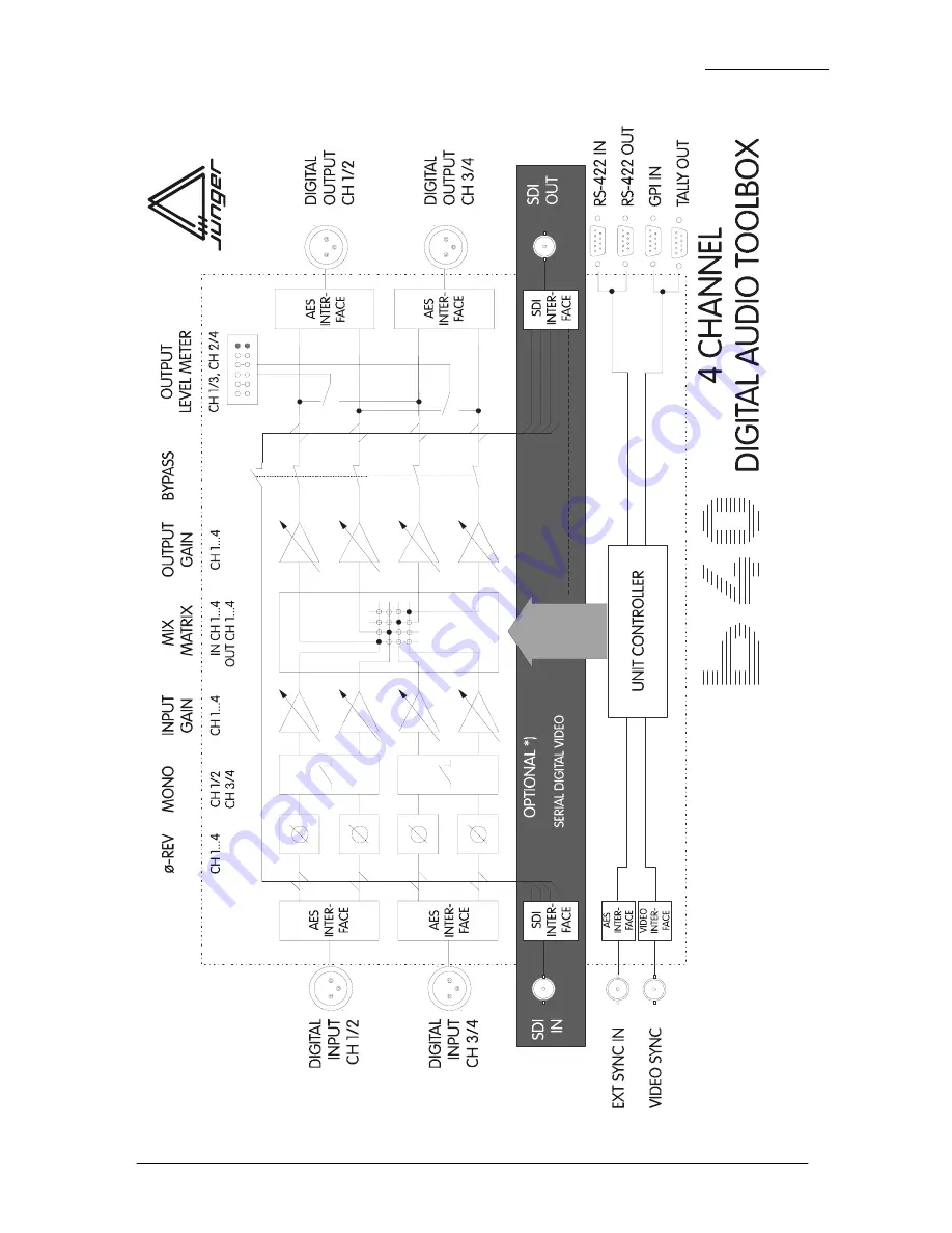
BLOCK DIAGRAM
Operation manual b40, chapter 3 -installation- page 3-6
Страница 1: ...DIGITAL AUDIO TOOLBOX model b40 operations manual rev 3 1 Justus von Liebig Stra e 7 12489 Berlin Germany Telefon 030 67 77 21 0 Fax 030 67 77 21 46 www junger audio com...
Страница 2: ...channel Digital Audio Toolbox b40 Not only you have aquired the latest generation of digital dynamic range processing but also a piece of equipment which is unique in its design and specification 0 P...
Страница 3: ...3 3 3 3 3 4 3 5 3 6 3 1 Unpack the unit 3 2 Power supply 3 3 Connections 3 4 Rack mounting 3 5 Operation safety 3 6 Synchronization of digital output 3 7 Remote Control 3 7 1 GPI Remote Control 3 7 2...
Страница 4: ...2 Error messages and trouble shooting 5 3 Initialization the unit 6 1 6 1 6 1 6 3 7 1 8 1 6 Application notes 6 1 B40 series with SDI interface 6 2 Basic working modes with SDI 6 3 Remote control wit...
Страница 5: ...panel b40 INPUT selection of digital input SYNC selection of sync input PRESET 1 4 storage and recall of presets 1 4 REV 180 phase reverse for ch1 2 or 3 4 MONO mono switching of ch1 2 or ch3 4 CH 1...
Страница 6: ...e 2 2 INPUT 1 4 selection of input channel matrix and then OUTPUT 1 4 selection of output channel to set or reset connecting points of the matrix output gain CH 1 4 selection push and adjustment turn...
Страница 7: ...AES 3 format 75 Ohm unbal connector BNC socket VIDEO input for video sync signal blackburst 75 Ohm unbal connector BNC socket SDI IN OUT only for SDI Version Input output for serial digital video ITU...
Страница 8: ...erial remote interface Front panel is locked Note DISABLE is only activated if serial remote control is connected ADDR Selection of the device address for serial remote 16 device addresses selectable...
Страница 9: ...jumper J1 on main board of the unit The 4 channel processors of b40 series fitted with SDI interface are compatibel with the standard SMPTE 272M AB They support 48 kHz synchronous audio sampling with...
Страница 10: ...ing all data of this group if it was already existing necessary if a new group should be embedded and if audio in other groups was embedded previously is matching ideally the structure which was gener...
Страница 11: ...40 is equipped with standard connectors see also chapter 3 Before connecting the digital audio toolbox b40 switch the power off at all connected units The digital audio toolbox b40 is made as standard...
Страница 12: ...tically The digital output signal can be clocked with the following clock frequencies CH 1 2 locks with the clock frequency of the input signal at digital input CH 1 2 AES EBU EXT SYNC locks with the...
Страница 13: ...e Logic I O Functions 1 PRESET1 L I call preset1 2 PRESET2 L I call preset2 3 PRESET3 L I call preset3 4 PRESET4 L I call preset4 5 FACTORY PRESET L I call factory preset not alterable 6 BYPASS L I by...
Страница 14: ...Logic I O Functions 1 PRESET1 H O preset1 recalled 2 PRESET2 H O preset2 recalled 3 PRESET3 H O preset3 recalled 4 PRESET4 H O preset4 recalled 5 OVERLOAD H O overlevel at digital output ch1 4 6 BYPA...
Страница 15: ...st be connected on both ends 5 1 9 6 REMOTE IN Pin Signal name Functions 1 DSR out Data set ready 2 DSR out 3 SENSE in Interrogation Remote 4 RXD out Receive data 5 RXD out 6 DTR in Data terminal read...
Страница 16: ...3 INSTALLATION 3 8 BLOCK DIAGRAM Operation manual b40 chapter 3 installation page 3 6...
Страница 17: ...is made by adjustment of various parameters and settings The description is made related to the functional blocks on the front panel 4 1 4 2 4 3 4 4 4 5 4 6 4 7 4 8 4 9 mode recalling and storing of...
Страница 18: ...parameters of REV MONO INPUT GAIN MATRIX and OUTPUT GAIN can be stored into presets Recall of presets preset buttons 1 4 recall of preset 1 4 Storage of presets preset buttons 1 4 after appr 3 sec of...
Страница 19: ...the OUTPUT buttons 1 selection of input channel by pushing related INPUT button 2 selection of requested output channel by pushing related OUTPUT button This procedure is to repeat up to all necessary...
Страница 20: ...level at the output occurs if digital audio samples at the maximum permissable positive or negative sample value occur at the digital output then the red clip LED at the extreme right hand end of the...
Страница 21: ...SAGES AND TROUBLE SHOOTING display error message remedies NO SYNC no sync at sync input connect the sync input selectable in SYNC field with valid input signal CH 1 2 sync on DIGITAL IN CH 1 2 EXT syn...
Страница 22: ...restarted Any button is to be held pressed in order to initialize the device during switch on of the device until the program started To the start of the program and at the completion of the displays...
Страница 23: ...is Group 1 with 48 kHz synchronous sampling Synchronous means that the audio clock is genlocked to the associated video Each channel can have up to 20 bits of resolution per audio sample The 4 channe...
Страница 24: ...6 APPLICATION NOTES operation manual b40 chapter 6 Application notes page 6 2...
Страница 25: ...e button only features of brc4x universal remote control panel RS 422 remote operation of several units up to 16 devices various models of b40series together are possible self detecting remote system...
Страница 26: ...75 Ohm coaxial data rate 270 Mb s 525 625 Line rate format serial digital component video 4 2 2 with embedded audio ITU R BT 601 SMPTE 272M A level 800 mV 10 equalisation appr 180 m Belden 8281 audio...
Страница 27: ...rallel remote level TTL connector 9 pin SUB D female Tally Out level TTL max 25mA connector 9 pin SUB D male GENERAL power consumption appr 15 VA dimensions 19 1 RU 250 mm depth weight appr 5 kg optio...
Страница 28: ...RRANTY AND SERVICE INFORMATION 8 J NGER AUDIO grants a two year warranty on the 4 channel digital audio toolbox b40 If the unit has to be serviced please send it ideally in the original box to J NGER...