background image

– 14 –

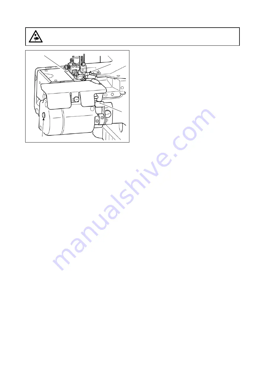
1)  Depress lever 

 until it will go no further. Moving knife 

  moves  to  the  position  which  is  lower  than  throat 

plate 

.

2)  Keeping  lever 

  held  in  the  fully-depressed  position, 

press button 

 to release lever 

.

3)  Moving knife 

 is fixed in the aforementioned position 

which is lower than the throat plate 

. To use moving 

knife 

 again, slightly depress lever 

. Moving knife 

 will be brought to the previous position and lever 


and button 

 will be returned to their home position by 

the spring.

13. HOW TO USE THE KNIFE CANCELLING MECHANISM

WARNING :

To protect against possible personal injury due to abrupt start of the machine, be sure to start the follow-

ing work after turning the power off and ascertaining that the motor is at rest.

Содержание MF-7900-E11

Страница 1: ...vi INSTRUCTION MANUAL MF 7900 E11...

Страница 2: ...ED KNIFE 4 7 ADJUSTMENT PROCEDURE OF CLOTH GUIDE 4 8 ADJUSTMENT PROCEDURE OF FRONT UP AMOUNT OF THE PRESSER FOOT 5 9 ADJUSTMENT PROCEDURE OF THE POSITION OF THE TAPE GUIDE 5 10 INSTALLING THE ACCESSOR...

Страница 3: ...ed waist elastic attaching of men s brief trunks etc Waist elastic width up to 40 mm Sewing speed Max 5 000 sti min provided with PL12 or PL13 at the time of intermittent operation Speed of stitch at...

Страница 4: ...sure of moving knife and fixed knife as low as possible within the range of smooth cutting of fabric Loosen setscrew of striker A and setscrew of striker B in the written order Shift striker B to the...

Страница 5: ...angle of mesh is until marker dot A is turned coun terclockwise to reach the horizontal posi tion If the lever is turned beyond the above the angle between the upper knife and the lower knife will inc...

Страница 6: ...justment of engagement again 6 REPLACEMENT PROCEDURE OF MOVING KNIFE AND FIXED KNIFE Adjust the position of cloth guide in accordance with the kinds and thickness of the fabric so that the hook knife...

Страница 7: ...OSITION OF THE TAPE GUIDE Loosen setscrew and move tape guide base to the right and left to adjust the position of the tape WARNING To protect against possible personal injury due to abrupt start of t...

Страница 8: ...and fix it with screws and 1 Install bottom roller plate with three wood screws For the installing position of the bottom roll er plate refer to the drawing of the table Fix front roller general asm...

Страница 9: ...er plate base refer to the drawing of the table 2 Install rear roller asm to rear roller plate base with screw M8 washer and clamp lever 5 Installing the suction pipe Fix suction pipe retaining plate...

Страница 10: ...eft in accordance with the elactic band width At this time make sure that the elactic band is put straight Then tighten screw Do not excessively tighten screws and Deformation of collars will be cause...

Страница 11: ...vertical position Loosen clamp lever adjust the position so that the elastic band is appropriately in accordance with the length of it and tighten clamp lever 4 Adjusting the position of the bottom ro...

Страница 12: ...prox 30 mm Then clamp le ver Fig 2 3 Adjusting the lateral position Loosen screw adjust the left edge of collar to the right hand side of the elastic and tighten screw At this time adjust so that left...

Страница 13: ...and and tighten screw 2 Adjusting the elastic guide A Approx 41 mm B Approx 60 A B 2 Adjusting the angle and length Loosen screw and adjust presser guide so that the distance from the bottom of instal...

Страница 14: ...he top surface of the cover Then tighten screw Fig 2 1 Adjusting the lateral position Loosen screw and screw and adjust presser bar so that the clearance between cloth presser and knife is 0 5 mm Then...

Страница 15: ...w and adjust stopper to the position before it comes in contact with lever Then tighten screw 3 mm 5 Adjusting the presser plate pressure Adjust the presser pressure by loosening screw and turning col...

Страница 16: ...which is lower than the throat plate To use moving knife again slightly depress lever Moving knife will be brought to the previous position and lever and button will be returned to their home position...

Страница 17: ...h 20 Drill a hole at the time of set up B 3 x 3 8 on the top surface depth 10 Drill a hole at the time of set up Rear roller mounting base hole C Drilled hole 17 D 7 x 3 8 on the bottom surface depth...

Страница 18: ...Drilled hole 17 D 5x 20 Passing through E 50 Passing through F 3 x 3 8 on the bottom surface depth 10 Drill a hole at the time of set up Bracket mounting hole G 2 x 3 8 on the bottom surface depth 10...

Отзывы: