background image


6


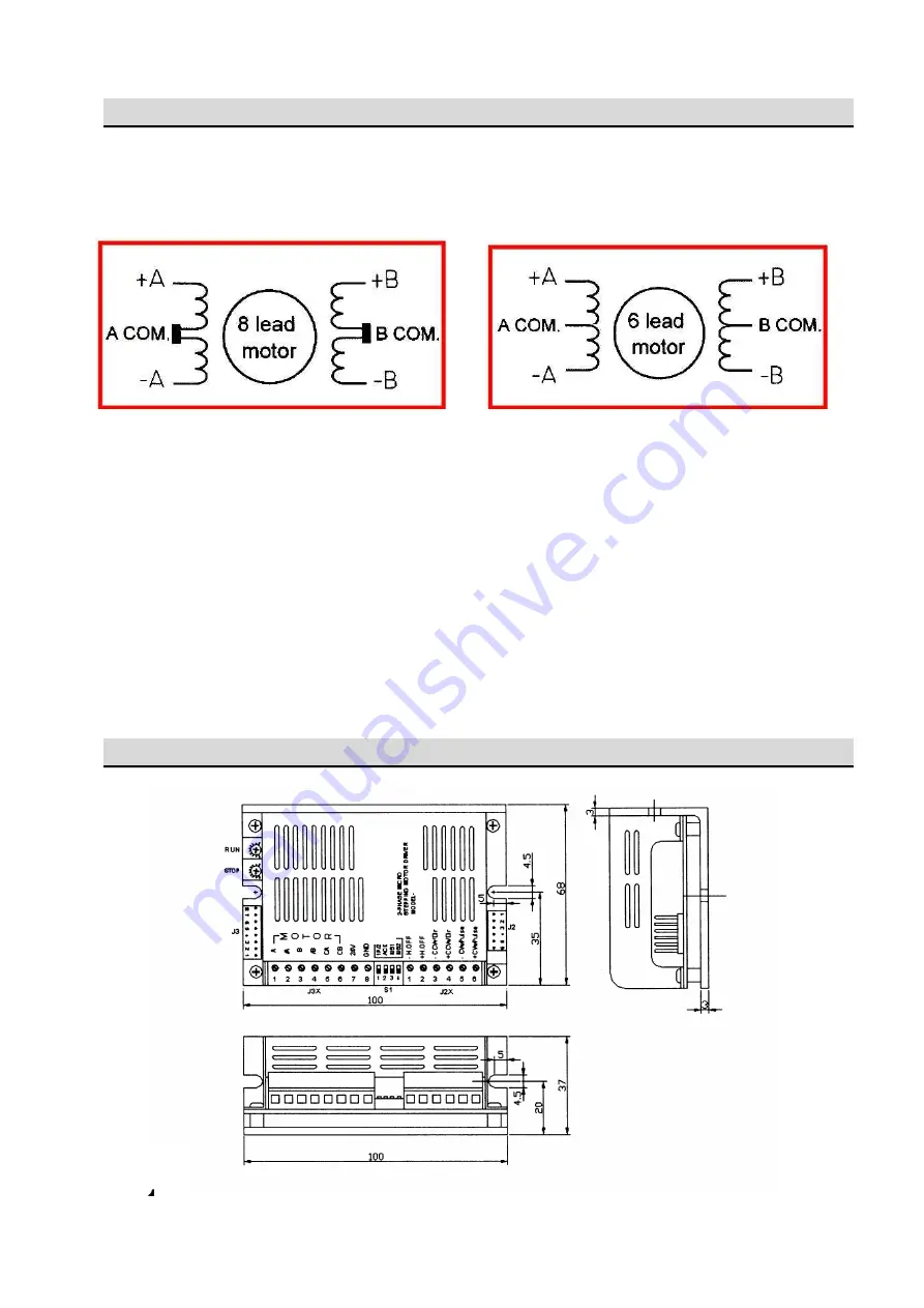
Wiring Diagrams                                                                                             

PMC2615 is a unipolar constant current driver, use a 6 wire or 8 wire motor is required.   


8wire connection                                                    6wire connection 


Notes on wiring: 

*For a stable operation, power supply of DC12V ~DC36V 4A (minimum) is required. 

*Be sure to power off while motor is being wired. 

*Wrong wiring or wire may damage the driver. 

*The external force cooling is required, if you the driver case temperature is higher than 55 degree C 

at normal operation. 

*Please use the driver at good ventilation environment. 

*Please do not use the driver at wet or the environment may have condensed water.   


7


Dimension                                                                                                         


Содержание PMC-2615-16

Страница 1: ...P MOTOR DRIVER USER S MANUAL V1 1 JS AUTOMATION CORP 100 6 6F No 100 Zhongxing Rd Xizhi Dist New Taipei City Taiwan TEL 886 2 2647 6936 FAX 886 2 2647 6940 http www automation com tw E mail control ca...

Страница 2: ...1 Correction record Version Record 1 1 Add Correction record and Warranty...

Страница 3: ...2 Contents 1 Features 4 2 Specifications 4 3 I O Functions 5 4 LED indicator 6 5 CONTROL SIGNAL 6 6 Wiring Diagrams 7 7 Dimension 7...

Страница 4: ...tation of the liability of JS automation Corp will apply regardless of the form of action whether in contract or tort including negligence Any action against JS automation Corp must be brought within...

Страница 5: ...source DC12V to DC36V 4A min Driving Mode PWM Switching unipolar with Constant Current Driving Maximum Current 1 5A Phase Resolution 200 400 800 1600 pulse rev selectable Input Signal CW and CCW Puls...

Страница 6: ...topped for more than 0 5s the motor current will decrease to the adjustment value J3X Connectors 1 Motor A 2 Motor A 3 Motor B 4 Motor B 5 Motor Common A 6 Motor Common B 7 8 DC power input 12VDC 36VD...

Страница 7: ...to disable this function 3 4 MS1 MS2 Micro step mode selection 4 LED indicator 4 1 POWER green LED power OK will light 5 CONTROL SIGNAL 5 1 The control signal is isolated by photo isolator and the ex...

Страница 8: ...f DC12V DC36V 4A minimum is required Be sure to power off while motor is being wired Wrong wiring or wire may damage the driver The external force cooling is required if you the driver case temperatur...

Отзывы: