background image

NSVS670 Nov. 2004 


5.2±0.2

4.5

±

0.2

1

.

5

±

0.2

(1.2)

(1.55)

(

1.27)

(1.2

7)

(0.

75)

(0.8

)

J36

420

(1)

(a)

( b)

(2)

(3)

[8

×

]

[2

×

]

[5X]

1.

27

1.

27

1.

0

5.

3

1.6

1.0

6.0

Via-Hole(

Φ

0.3)

[6x]

[6

x

]

[3x]


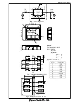
Marking 

(1) Manufacture’s Mark 

(2) Lot Number 

 (a) 

Year 

 (b) 

Month 

  *Oct.--- 

   Nov.--- 

   Dec.--- 

(3) Part number Mark 

Pin no. 

Connection 

1 GND 

2 IN/OUT 

3 GND 

4 GND 

5 GND 

6 OUT/IN 

7 GND 

8 GND 

Fig.1 Measuring circuit

Fig.2 Package dimensions (in mm)

Fig.3 Desirable land area (in mm)

1

2

3

4

5

6

7

8

SAW

IN 

50


OUT 

50


Содержание NSVS670

Страница 1: ...0 430MHz 4 0dB max 3 1dB Response Variation 410 430MHz 2 0dB max 0 9dB Input and Output VSWR 410 430MHz 2 5 max 1 7 380MHz 40dB min 45dB Out of Band Rejection Relative to Through Level 500MHz 40dB min 50dB Operating Temperature Range 10 60ºC Table 2 Maximum Ratings Item Rating Maximum Input Power 20dBm Maximum DC Voltage 7 5V Operating Temperature Range 10 60ºC Storage Temperature 30 85ºC JRC SAW ...

Страница 2: ... 3 1 6 1 0 6 0 Via Hole Φ 0 3 6x 6x 3x Marking 1 Manufacture s Mark 2 Lot Number a Year b Month Oct X Nov Y Dec Z 3 Part number Mark Pin no Connection 1 GND 2 IN OUT 3 GND 4 GND 5 GND 6 OUT IN 7 GND 8 GND Fig 1 Measuring circuit Fig 2 Package dimensions in mm Fig 3 Desirable land area in mm 1 2 3 4 5 6 7 8 SAW IN 50Ω OUT 50Ω ...

Страница 3: ... destruction to apply static electricity to this component do not apply static electricity or excessive voltage while assembling and measuring And do not transport this component with bare hand 7 As it might be a cause of degradation or destruction to apply D C voltage between each terminal apply D C voltage 7 5V max in actual circuit Note 1 This specification specifies the quality of this compone...

Страница 4: ...it 13 30 0 20 6 5 0 20 R0 3 4 0 76 2 54 1 4 0 8 12 2 54 0 15 Pin No Connection 1 GND PKG 2 GND PKG 3 GND PKG 4 GND PKG 5 OUT IN 6 GND signal 7 GND PKG 8 GND PKG 9 GND PKG 10 GND PKG 11 IN OUT 12 GND signal 2 0 max 1 a b 3 Marking 1 Manufacture s Mark 2 Lot Number a Year b Month Oct X Nov Y Dec Z c Date 1 9 0 10 19 1 20 31 2 3 Part Number Mark 1 26 0 13 12 12 2 54 R0 3 2 54 0 15 2 1 2 3 4 5 6 7 8 9...

Отзывы: