


3.4 GENERAL RADAR OPERATION
3
-
25
3
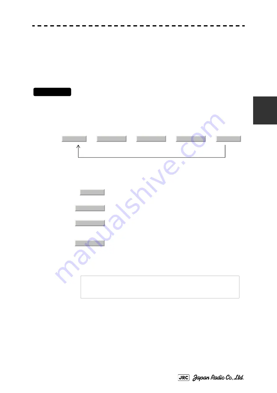
3.4.3
Target Enhance (ENH)
The dimension of video display is enlarged to enhance a target.
Procedures
1)
Left-click the ENH button located at the lower left of the radar
display.
The target enlargement levels are switched.
⇒
⇒
⇒
⇒
In general, ENH Level1 or ENH Level2 should be selected.
Effect of target enlargement
:Expansion
off
Select this mode particularly when
resolution is required.
:Expansion small
Select this mode in general. Radar echoes
are expanded by 1 scale in all directions.
:Expansion
medium Select
this
mode to easily view the radar
video. Radar echoes are expanded by 2
scales in all directions on the display.
Expansion large
Select this mode to detect small targets
such as buoys. The expansion near a
screen center is added to ENH Level2.
NOTE:
When ENH Level3 is selected, sea clutter returns and rain/
snow clutter returns are apt to be expanded. When using this
expansion mode, operate [SEA] dial and [RAIN] dial to
suppress sea clutter returns and rain/snow clutter returns.
ENH Off
ENH Level1
ENH Level2
ENH Level3
ENH Off
ENH Off
ENH Level1
ENH Level2
ENH Level3
Содержание JMA-9110-6XA
Страница 2: ......
Страница 19: ...xvii NQE 3141 4A 8A Interswitch Unit NQE 3167 Power Control Unit Warning Label Warning Label...
Страница 21: ...xix NKE 1139 1130 Scanner Unit NTG 3230 3225 Transmitter Receiver Unit Warning Label Warning Label...
Страница 26: ...xxiv Display Unit Type NCD 4990 Stand alone type Interswitch Unit Type NQE 3141 4A...
Страница 44: ......
Страница 46: ......
Страница 82: ...1 36 JMA 9100 Instruction Manual 1 GENERAL AND EQUIPMENT COMPOSITION 1 5 GENERAL SYSTEM DIAGRAMS...
Страница 84: ......
Страница 116: ...2 32 JMA 9100 Instruction Manual 2 CONTROL PANEL KEYS and SOFTWARE BUTTONS 2 3 FUNCTIONS OF SOFTWARE BUTTONS...
Страница 120: ......
Страница 248: ......
Страница 270: ...4 22 JMA 9100 Instruction Manual 4 MEASUREMENT OF RANGE AND BEARING 4 2 MEASUREMENT OF RANGE AND BEARING...


