background image


Jovy Systems® Limited 

User Manual 

UM1501SLD01 

Revision  

1.00 

Date 

August 2015  


Page | 13  


7.


Software Mode 

The software of the station is used to define the desired operating temperatures. 

a)


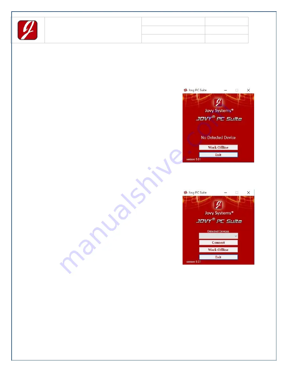
Offline Mode 

 
If the software is opened without 
connecting the station, or if it’s 
connected but not turned on, the 
software’s menu will show only “Work 
Offline” and “Exit”. 


b)


Online Mode 


When the station is properly 
connected via the USB and is turned 
on, the software menu interface when 
opened will look like the opposite 
picture. 
 
The serial Number will be displayed in 
the first field. 
 
Connect will lead directly into the 
software.


Содержание iSolder 40

Страница 1: ...Jovy Systems Limited Jovy Systems Limited iSolder 40 User Manual...

Страница 2: ...ns 3 Initial set up 4 Packing list 4 How to use 5 Modes Guideline 7 1 Heating up mode 7 2 Operating mode 7 3 User mode 8 4 Debug mode 9 5 Sleep mode 11 6 Power saving mode 11 7 Software Mode 13 Tip ca...

Страница 3: ...ted work space and preferably use a smoke absorber appliance Do not use the equipment or the hand piece with wet hands Connect only to properly grounded outlets to prevent risk of electric shock or eq...

Страница 4: ...losure Temperature 53 C Input Line voltage 115VAC 60Hz 230VAC 50Hz Output voltage 24VAC Power Consumption 50 Watts max Dimensions L W H mm 188 x 144 x 120 Power chord length Plug type 1 8 meters Hand...

Страница 5: ...August 2015 Page 4 Initial set up Packing list Item Quantity Code Solder Station 1 JV SSS Main tip 1 JV TP1 Hand piece holder 1 Cleaning sponge 1 Protective Pad 1 Power cord 1 Multilingual Startup Gu...

Страница 6: ...110VAC 60Hz or 220VAC 50Hz 2 Place and arrange the iSolder 40 with all other parts in a convenient location in your workspace 3 Insert the desired tip into the hand piece to end fastening click heard...

Страница 7: ...nto electricity supply and switch on the iSolder 40 5 If the tip is inserted correctly a green led indicator will start flashing Heating up mode If the tip inserted wrongly the led color will be red 6...

Страница 8: ...troller is active and sensing the fast flashing Green Led will be seen from time to time Make sure that the toggle button is upwards Mode 2 when starting the station otherwise the station will enter i...

Страница 9: ...lt mode will be the Automatic iControl mode A User Mode 1 To enter User Mode 1 default starting mode make sure that button s position is downwards otherwise press the button until its position is down...

Страница 10: ...e the station to the latest firmware version make sure to press the toggle button so that its position is hold downwards connect the iSolder 40 station to the PC using the USB port and then power the...

Страница 11: ...appear showing the Name of the station and the Serial Number Choosing import will open a browse window to choose the location of the firmware After the Firmware Upgrade file is chosen a confirmation...

Страница 12: ...ort off To get out from sleep mode and turn to operating mode move the hand piece from the holder and wait until the iControl automatically senses and update the status from Sleep to Operating mode 6...

Страница 13: ...tate is a flashing red led short on short off The difference between the sleep mode led color indicator and the auto shut down mode led color indicator is the speed of flashing For sleep mode the led...

Страница 14: ...software is opened without connecting the station or if it s connected but not turned on the software s menu will show only Work Offline and Exit b Online Mode When the station is properly connected v...

Страница 15: ...s from the station to the software d Edit Choosing Edit will allow the software to Edit the saved configurations and adjust the temperatures of both modes as desired After Editing the configurations o...

Страница 16: ...Revision 1 00 Date August 2015 Page 15 While if the temperature ranges Highest Temp and Lowest Temp are out of the range an error message will appear e Default Choosing Default will restore both of th...

Страница 17: ...Jovy Systems Limited User Manual UM1501SLD01 Revision 1 00 Date August 2015 Page 16 Tip care and selection Available tips for iSolder 40 JV TP1 JV TP2 JV TP3 JV TP4 JV TP5 JV TP6...

Страница 18: ...percentage of soldering area to tip active area is 2 1 Tip care guide for longer life time Clean the tip by wiping it with a wet sponge and slightly drag it out after each use Never use excessive mec...

Страница 19: ...ng using solder wire flux cored Make sure that the tip type is compatible to the application as explained above in tip selection section with the solder material mass to avoid process failure tip dama...

Страница 20: ...ovy Systems Limited User Manual UM1501SLD01 Revision 1 00 Date August 2015 Page 19 Sample applications for the iSolder 40 main tip SMT D SMD SMD Any type of soldering material Heavy junctions THT D SM...

Страница 21: ...r pricing and availability Jovy Systems warrants the iSolder 40 against any manufacturing defects for one 1 year from the date of purchase by the original owner If the product defected within the warr...

Страница 22: ...support As we always care about user satisfaction we have many support ways in the following points Many profiles for the common applications White papers Videos Live support through SKYPE We also sup...

Отзывы: