Doc. No.: 84145 Rev. L
jotron.com
Page 31 of 40
Test procedure instructions are also indicated on the
product label.
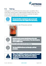
Testing of the Tron SART20 is done using the ships own 3 cm X-band radar.
Alternatively, a radar or a nearby ship can be used to test the unit. A ship-
to-ship VHF channel should then be used to confirm operation.
The radar display will show different patterns depending on the range to
the unit.
When the unit is located close to the radar the signals will appear as rings
on the radar display. The rings may be broken in some sectors, depending
on the construction of the ship and other obstacles, and does not indicate
an error in the unit. Placing it further away will reduce the signals to 12
dots on the radar display, showing the direction to the unit.
Typical display when
Tron SART20 is located
near (<0.2NM) the
radar. Radar range is
10NM. Rings are off.
Typical display when
Tron SART20 is located
close (1NM) to the
radar. Radar range is
10NM. Rings are at
2NM.
Typical display when
Tron SART20 is located
away (>2NM) from the
radar. Radar range is
10NM. Rings are at
2NM.
Radars often have a special function to optimize reception of radar SART,
either in TEST or ON. If the radar has this function, then it will be detuned
out of the best tuning condition, and erases or weakens all normal radar
echoes, however, SART echoes are not erased because SART frequencies
scans over all the X-band from 9.2 to 9.5 GHz. When this function is
Содержание Tron SART20
Страница 1: ...Tron SART20 Radar Transponder User Manual...
Страница 2: ...This page is intentionally left blank...
Страница 12: ...Doc No 84145 Rev L jotron com Page 12 of 40 Figure 1 Tron SART20...
Страница 39: ...Doc No 84145 Rev L jotron com Page 39 of 40...


