background image

14

OPERATION

FIG. 12

FIG. 11

02710

AT TACH MENT 

CLUTCH SWITCH

"DISENGAGED" 

PO SI TION

AT TACH MENT

LIFT LEVER

HIGH PO SI TION

"EN GAGED" 

PO SI TION

LOW

POSITION

TO OPERATE MOWER (See Fig. 12)

Your tractor  is equipped with an operator presence sensing 

switch.  Any attempt by the operator to leave the seat with the 

engine running and the attachment clutch engaged will shut off 

the engine. You must remain fully and centrally positioned in the 

seat to prevent the engine from hesitating or cutting off when 

operating your equipment on rough, rolling terrain or hills.
•  Select desired height of cut.
•  Lower mower with attachment lift control.
•  Start mower blades by engaging attachment clutch 

control.

•  TO STOP MOWER BLADES - disengage attachment 

clutch con trol.

CAUTION:  Do not operate the mower 

without either the en tire grass catcher, 

on mowers so equipped, or the deflector 

shield in place.

TO ADJUST GAUGE WHEELS (See Fig. 11)

Gauge wheels  are properly adjusted when they are slightly 

off the ground when mower is at the desired cutting height 

in operating position. Gauge wheels then keep the deck 

in proper position to help prevent scalping in most terrain 

conditions. 

NOTE:

Adjust gauge wheels with tractor on a flat level 

surface.
•  Adjust mower to desired cutting height (See “TO AD-

 JUST MOWER CUT TING HEIGHT” in the Operation 

sec tion of this manual).

•  With mower in desired height of cut po si tion, gauge 

wheels should be assembled so they are slightly off 

the ground. In stall gauge wheel in appropriate hole 

with shoulder bolt, 3/8 washer, and 3/8-16 locknut and 

tighten se cure ly.

• 

Repeat for opposite side installing gauge wheel in same 

adjustment hole.

SHOULDER BOLT

LOCKNUT

3/8 WASHER

REVERSE OPERATION SYSTEM (ROS)

Your tractor is equipped with a Reverse Operation System 

(ROS). Any attempt by the operator to travel in the reverse 

direction with the attachment clutch engaged will shut off 

the engine unless ignition key is placed in the ROS "ON" 

position.

 WARNING

:

  Backing up with the attachment clutch en-

gaged while mowing is strongly discouraged. Turning the 

ROS "ON", to allow reverse operation with the attachment 

clutch engaged, should only be done when the operator 

decides it is necessary to reposition the machine with the 

attachment engaged. 

Do not mow in reverse unless 

absolutely necessary

.

USING THE REVERSE OPERATION SYSTEM  

(See Fig. 13)

Only use if you are certain no children or other bystanders 

will enter the mowing area.
•  Move motion control lever to neutral (N) position.
• 

With engine running, turn ignition key counterclockwise 

to ROS "ON" position.

•  Look down and behind before and while backing.
• 

Slowly move motion control lever to reverse (R) po si tion 

to start movement.

•  When use of the ROS is no longer needed, turn the 

ignition key clockwise to engine "ON" position.

ROS "ON" Position

Engine "ON" Position

(Normal Operating)

02828

FIG. 13

Содержание LT2218CMA

Страница 1: ...TRACTOR ALWAYS WEAR EYE PROTECTION DURING OPERATION WARNING Read this Manual and follow all Warnings and Safety Instructions Failure to do so can result in serious injury IMPORTANT MANUAL Do Not Throw Away 410262 03 14 07 CL Printed in U S A ...

Страница 2: ... catcher or unclogging the discharge guard Operate machine only in daylight or good artificial light Do not operate the machine while under the influence of alcohol or drugs Watch for traffic when operating near or crossing road ways Use extra care when loading or unloading the machine into a trailer or truck Always wear eye protection when operating ma chine Data indicates that operators age 60 y...

Страница 3: ...signed for towing Do not attach towed equipment except at the hitch point Follow the manufacturer s recommendation for weight limits for towed equipment and towing on slopes Never allow children or others in or on towed equip ment On slopes the weight of the towed equipment may cause loss of traction and loss of control Travel slowly and allow extra distance to stop V SERVICE SAFE HANDLING OF GASO...

Страница 4: ...d in effective working order by the operator In the state of California the above is required by law Section 4442 of the California Public Resources Code Other states may have similar laws Federal laws apply on federal lands CUSTOMER RESPONSIBILITIES Read and observe the safety rules Follow a regular schedule in maintaining caring for and using your tractor Follow the instructions under the Mainte...

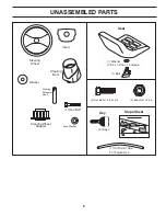
Страница 5: ...MBLED PARTS OLT 7ASHER X X AUGE 3EAT EYS 3LOPE 3HEET EY IL RAIN 4UBE OR UTURE 5SE EX OLTS X EPS UT Steering Wheel Steering Wheel Adapter Steering Boot 7ASHER NSERT ª EXª OLT OCKª7ASHER Steering Extension Shaft ...

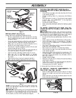
Страница 6: ...wheel TO REMOVE TRACTOR FROM CAR TON UNPACK CARTON Remove all accessible loose parts and parts cartons from carton Cut along dashed lines on all four panels of carton Remove end panels and lay side panels flat Check for any additional loose parts or cartons and remove Your new tractor has been assembled at the factory with exception of those parts left unassembled for shipping purposes To ensure s...

Страница 7: ...his manual Be sure tractor is in a well ventilated area Be sure the area in front of tractor is clear of other people and objects TO ROLL TRACTOR OFF SKID See Op eration section for location and function of controls Press lift lever plunger and raise attachment lift lever to its highest position Release parking brake by depressing clutch brake pedal Place freewheel control in transmission disengag...

Страница 8: ...ate install the bagger support tube to the back plate as shown Tighten securely Install the two upper support brackets through the back plate and to the chassis install the clevis pin 10x17mm and secure with retainer spring Assemble both support brackets to the outside of the bagger support tube using two each 3 8 x 63 5mm hex bolts13 32 I D flatwashersand3 8locknutsfromparts bag Tighten securely ...

Страница 9: ... the nuts securely VERTICAL ADJUSTMENT Slightly loosen the nuts securing the vertical adjust ment brackets Loosen only enough so the brackets keep their position but allow them to be moved Move the brackets the amount up or down you wish the bag assembly to move Retighten the nuts securely Reinstall the bagger assembly and check the bagger to fender fit If necessary repeat the procedure until prop...

Страница 10: ... fresh clean regular unleaded gasoline Become familiar with all controls their location and function Operate them before you start the engine Be sure brake system is in safe operating condition It is important to purge the transmission before oper ating your tractor for the first time Follow proper start ing and transmission purging instructions See TO START ENGINE and PURGE TRANSMISSION in the Op...

Страница 11: ... safety inform ation about hazards which can result in death serious injury and or property damage DANGER indicates a hazard which if not avoided will result in death or serious injury WARNING indicates a hazard which if not avoided could result in death or serious injury CAUTION indicates a hazard which if not avoided might result in minor or moderate injury CAUTION when used without the alert sy...

Страница 12: ...hingandbrak ing the tractor and starting the engine FREEWHEEL CONTROL Disengages transmission for pushing or slowly towing the tractor with the engine off HEIGHTADJUSTMENTKNOB Usedtoadjustthemower cutting height IGNITION SWITCH Used for starting and stopping the engine LIFT LEVER PLUNGER Used to release attachment lift lever when changing its position LIGHT SWITCH Turns the headlights on and off M...

Страница 13: ...eight is controlled by turning the height ad justment knob in desired direction Turn knob clockwise to raise cutting height Turn knob counterclockwise to lower cutting height The cutting height range is approximately 1 1 2 to 4 The heights are measured from the ground to the blade tip with theenginenotrunning Theseheightsareapproximateand may vary depending upon soil conditions height of grass and...

Страница 14: ...tion of this manual With mower in desired height of cut position gauge wheels should be assembled so they are slightly off the ground Install gauge wheel in appropriate hole with shoulder bolt 3 8 washer and 3 8 16 locknut and tighten securely Repeatforoppositesideinstallinggaugewheelinsame adjustment hole SHOULDER BOLT LOCKNUT 3 8 WASHER REVERSE OPERATION SYSTEM ROS Your tractor is equipped with ...

Страница 15: ...fications of the manufacturer of your trac tor Use common sense when towing Too heavy of a load while on a slope is dangerous Tires can lose traction with the ground and cause you to lose control of your tractor 02219 TO TRANSPORT See Figs 9 and 14 When pushing or towing your tractor be sure to disengage transmission by placing freewheel control in freewheeling position Free wheel control is locat...

Страница 16: ...apped air inside the transmission which may have de veloped during shipping of your tractor TO START ENGINE See Fig 9 When starting the engine for the first time or if the engine has run out of fuel it will take extra cranking time to move fuel from the tank to the engine Besurefreewheelcontrolisinthetransmissionengaged position Sit on seat in operating position depress clutch brake pedal and set ...

Страница 17: ...in and give best performance of the attachment being used OPERATION Certaintypesofgrassandgrassconditionsmayrequire that an area be mulched a second time to completely hide the clippings When doing a second cut mow across perpendicular to the first cut path Change your cutting pattern from week to week Mow northtosouthoneweekthenchangetoeasttowestthe next week This will help prevent matting and gr...

Страница 18: ... deflector to allow mower to operate You are now ready to begin mulching BAGGING See Fig 18 Place deck into the high cut position Remove the rear discharge deflector or mulching plug Insert the discharge chute into the opening in the backplate and onto the mower deck adaptor Attachthechutetothetractorbyhookingthetwostraps to the flange of the chute NOTE Thestraphookmustgothroughthedischargechute o...

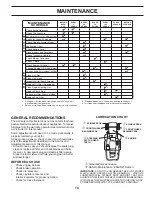
Страница 19: ...n air filter assure proper air fuel mixture and help your engine run better and last longer BEFORE EACH USE Check engine oil level Check brake operation Check tire pressure Check operator presence and interlock systems for proper operation Check for loose fasteners T R A C T 0 R Inspect Muffler Spark Arrester Clean Air Filter Change Engine Oil with oil filter Replace Air Filter Paper Cartridge Rep...

Страница 20: ... gasoline oil or insect control chemi cals which can harm rubber Avoid stumps stones deep ruts sharp objects and other hazards that may cause tire damage NOTE To seal tire punctures and prevent flat tires due to slow leaks tire sealant may be purchased from your local parts dealer Tire sealant also prevents tire dry rot and corrosion OPERATORPRESENCESYSTEMANDREVERSE OPERATION SYSTEM ROS See Fig 19...

Страница 21: ... clean to assure proper cooling Do not attempt to clean fan or transmission while engine is running or while the transmission is hot To prevent pos sible damage to seals do not use high pressure water or steam to clean transaxle Inspect cooling fan to be sure fan blades are intact and clean Inspect cooling fins for dirt grass clippings and other materials Topreventdamagetoseals donotusecom pressed...

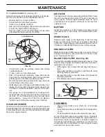
Страница 22: ...cap dipstick for checking level Insert dipstick into the tube and rest the oil fill cap on the tube Do not thread the cap onto the tube when taking reading Keep oil at FULL line on dipstick Tighten cap onto the tube securely when finished MUFFLER Inspect and replace corroded muffler and spark arrester if equipped as it could create a fire hazard and or dam age SPARK PLUGS Replace spark plugs at th...

Страница 23: ...into clutch pulley groove Installleftfrontlinkintothelefthandfrontmowerbracket retain with single loop retainer springs as shown Slide right side of mower back and install right front link into right hand front mower bracket retain with single loop retainer springs Placethesuspensionarmsonmowerpins ifnecessary rock and raise front of mower to align mower pins with the holes in suspension arms Reta...

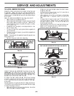
Страница 24: ...WILL STAY LEVEL SIDE TO SIDE To obtain the best cutting results the mower housing should be adjusted so that the front is approximately 1 8 to 1 2 lower than the rear when the mower is in its high est position Checkadjustmentonrightsideoftractor Measuredistance D directly in front and behind the mandrel at bottom edge of mower housing as shown Before making any necessary adjustments check that bot...

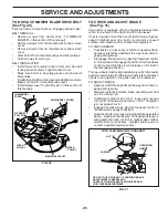
Страница 25: ...ance between brake operating arm and nut A on brake rod If distance is other than 1 9 16 loosen jam nut and turn nut A until distance becomes 1 9 16 Retighten jam nut against nut A Engage transmission by placing freewheel control in transmission engaged position Road test tractor for proper stopping distance as stated above Readjust if necessary If stopping distance is still greater than five 5 fe...

Страница 26: ...reeps repeat above steps until satis fied TRANSMISSION REMOVAL REPLACEMENT Should your transmission require removal for service or replacement it should be purged after reinstallation and beforeoperatingthetractor See PURGETRANSMISSION in the Operation section of this manual TO REPLACE MOTION DRIVE BELT See Fig 32 Park the tractor on level surface Engage parking brake For assistance there is a bel...

Страница 27: ...and in front of tractor Grasp hood at sides tilt toward engine and lift off of tractor To replace reverse above procedure ENGINE TO ADJUST THROTTLE CONTROL CABLE The throttle control has been preset at the factory and adjustment should not be necessary If adjustment is necessary see engine manual TO ADJUST CARBURETOR Thecarburetorhasbeenpresetatthefactoryandadjustment shouldnotbenecessary However ...

Страница 28: ...FUELSYSTEMPARTSSUCH AS CARBURETOR FUEL FILTER FUEL HOSE OR TANK DURING STORAGE ALSO EXPERIENCE INDICATES THAT ALCOHOL BLENDED FUELS CALLED GASOHOL OR USING ETHANOLORMETHANOL CANATTRACTMOISTUREWHICH LEADSTOSEPARATIONANDFORMATIONOFACIDSDURING STORAGE ACIDIC GAS CAN DAMAGE THE FUEL SYSTEM OF AN ENGINE WHILE IN STORAGE Empty the fuel tank by starting the engine and let it run until the fuel lines and ...

Страница 29: ...ignition switch 7 Check replace ignition switch 8 Faulty solenoid or starter 8 Check replace solenoid or starter 9 Faulty operator presence switch es 9 Contact an authorized service center department Engine clicks but will not 1 Weak or dead battery 1 Recharge or replace battery start 2 Corroded battery terminals 2 Clean battery terminals 3 Loose or damaged wiring 3 Check all wiring 4 Faulty solen...

Страница 30: ... of mower housing 8 Mower drive belt worn 8 Replace mower drive belt 9 Blades improperly installed 9 Reinstall blades sharp edge down 10 Improper blades used 10 Replace with blades listed in this manual 11 Clogged mower deck vent holes from buildup of 11 Clean around mandrels to open vent holes grass leaves and trash around mandrels Headlight s not working 1 Light switch is OFF 1 Turn light switch...

Страница 31: ... never across the face Do not mow slopes greater than 15 degrees Make turns gradually to prevent tipping or loss of control Exercise extreme caution when changing direction on slopes 1 Fold this page along dotted line indicated above 2 Hold page before you so that its left edge is vertically parallel to a tree trunk or other upright structure 3 Sight across the fold in the direction of hill slope ...

Страница 32: ...ng information a Model Number Manufacturer s I D Number b Description of part NOTE HOP provides parts and service through its authorized distributors and dealers therefore all requests for parts and service should be directed to your local dealer s The philosophy of HOP is to continually improve all of its products If the operating characteristics or the appearance of your product differs from tho...

Отзывы: