


- 9 -
7.Display control
7.1 Navigation in the Menu
7.
2 Menu Maps
Using the buttons or touch screen, and
this
can
be simply and easily set the address code and
code.
functions
If you view or
modify
the
lighting
feature
set
,
then
press
ENTER
button
,
the display
will
enter the
menu
interface
.
Both
there
is
sub menu corresponding to the functional operation of the main menu
.
Each of the
menus is
representative
of
the
specific
features of
the lamp
.
The specific
contents shows
as
the
table
menu
below
.
Set or browse lighting function, press UP or DOWN button.
Press ENTER to save your changes or enter the submenu
.
Press the UP or
DOWN can change the nume-
rical
(
increase
or
decrease
in
value).
Press the MODE button to return to menu
.
Set a time 0 to 10 minutes automatically exit menu interface
and close the screen.
If
there is a channel failure
in
the reset
process
,
the LCD
screen
will
display
the
corresponding
fault
information
,
can
be
compared
to the information
content
of
the
lamp
to be
amended
,
if
in doubt
,
consult
the
relevant technical
personnel
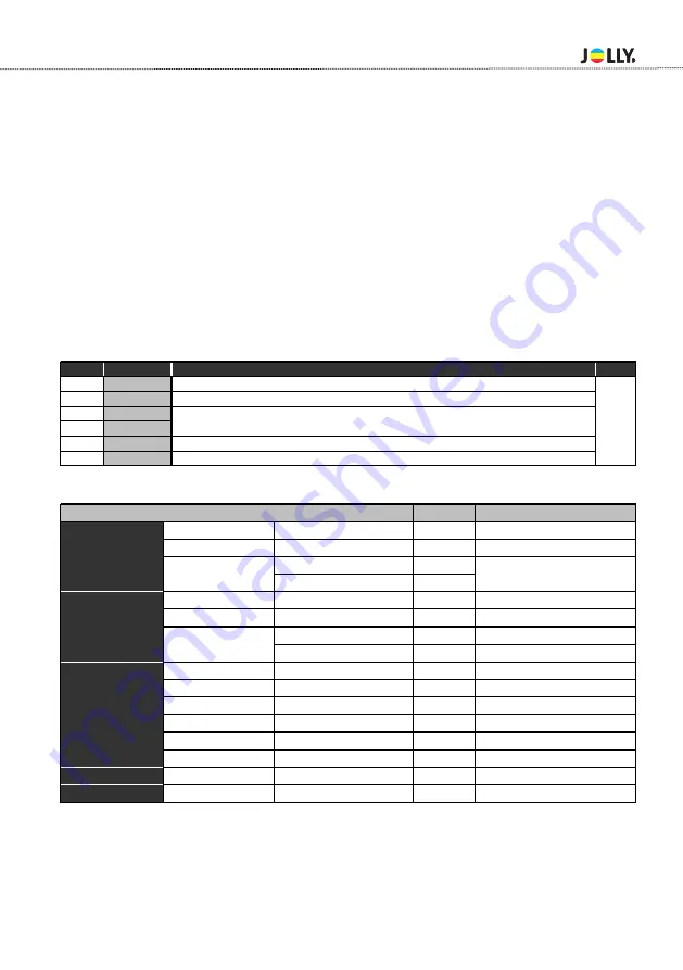
. -(
Error
List
)
CODE # ERRO INFO
CHECK MEASURMENT
NOTE
E01
SpiErr
Check the communication signal 25Q16 flash chip & memory IC
E02
PrgErr 1
Display firmware loading failed, load it again。
E03
BD1Err
E04
McuBusErr
E05
BD1CrcErr
LED driver firmware loading failed, load it again。
E06
Temp Err
Check the welding of Temp IC
Check the communication signal& welding of communication chip
RESET
ERROR
Remark
DMX Address
001~XXX
Fixture Id
0001~999
Mode 1
1-4
Mode 2
1-6
Auto Lamp ON
ON/OFF
Defaul ON
DMX Lamp
ON/OFF
Defaul ON
DSP.Sleep
0-10m
DSP.Contrast
Fixture Hours
XXXXX h XX m
Total working hours
Reset Times
lnput Password XXXX
DMX Monitor
Temperature
xxC
Error List
Error details
DMX Diagnostic
DMX Diagnostic
Manual Control
Channel
Chanel Testing
Advanced
Factory
ON/OFF
Reset to orignal parameters
Set Up
Channel Mode
Defaul 1
Information
Personality
Display
Содержание LP-H400
Страница 1: ...USER MANUAL LP H400 Version 1 0...
Страница 2: ......
Страница 12: ...6 Dimension 8 227 150 30 268 275 516 199 277...
Страница 17: ......