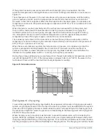
4. After the tubes have been corked for 12 to 24 hours, carefully test each tube. Two men
work at both ends of the evaporator, with one man removing corks at one end, and the
other at the opposite end to remove corks and handle the leak detector. Start with the top
row of tubes in the section being investigated. Remove the corks at the ends of one tube
simultaneously and insert the exploring tube for 5 seconds – this is long enough to draw into
the detector any refrigerant gas that might have leaked through the tube walls. A fan placed
at the end of the evaporator opposite the detector ensures that any leakage travels through
the tube to the detector.
5. Mark any leaking tubes for later identification.
6. If any of the tube sheet joints are leaking, the leak should be indicated by the detector. If
a tube sheet leak is suspected, its exact location can be found by using a soap solution. A
continuous buildup of bubbles around a tube indicates a tube sheet leak.
Compressor
Maintenance for the compressor assembly consists of completing the following checks:
•
checking the operation of the oil return system and changing the dehydrator
•
checking and changing the oil
•
checking and changing the oil filters
•
checking the operation of the oil heater
•
checking the operation of the oil pump
•
observing the operation of the compressor
Internal wearing of compressor parts could be a serious problem caused by incorrect lubrication,
brought about by restricted oil lines, passages, or dirty oil filters. If the unit is shutting down on
high oil temperature (HOT) or low oil pressure (OP), change the oil filter element. Examine the oil
filter element for the presence of aluminum particles. Aluminum gas seal rings can contact the
impeller and account for some aluminum particles to accumulate in the oil filter, especially during
the initial start up and first several months of operation. However, if aluminum particles continue
to accumulate and the same conditions continue to stop the unit operation after a new filter is
installed, notify the nearest Johnson Controls office to request the presence of a Johnson Controls
Service Technician.
Electrical controls
For information covering the OptiView™ Control Center operation, refer to the
OptiView™ Control
Center – Operation and Maintenance (Form 160.54-O1)
.
Model YK Style G R-134a or R-513A
40
Содержание York OptiView YK G Series
Страница 2: ...2 Model YK Style G R 134a or R 513A...
Страница 10: ...Figure 3 Refrigerant flow through chiller falling film evaporator Model YK Style G R 134a or R 513A 10...
Страница 11: ...Figure 4 Refrigerant flow through chiller flooded evaporator 11 Model YK Style G R 134a or R 513A...
Страница 21: ...Figure 10 System components rear view 21 Model YK Style G R 134a or R 513A...
Страница 22: ...Figure 11 Schematic drawing YK compressor lubrication system Model YK Style G R 134a or R 513A 22...

