JOHNSON CONTROLS
18
FORM 50.40-OM1 (713)
ISSUE DATE: 07/17/2013
SECTION 2 - OPERATION
TABLE 8 -
PRESSURE DIFFERENCE FOR DE-
TERMINING PRESENCE OF NON-CONDENSIBLE
GASES
REFRIGERANT
DIFFERENCE BETWEEN GAUGE
READING AND SATURATED
PRESSURE
PSIG
KPA
CFC-11
4
27.6
CFC-114
4
27.6
HFC-123
4
27.6
CFC-12
6
41.4
HFC-134a
6
41.4
CFC-500
8
55.1
HCFC-22
10
69.0
CFC-502
10
69.0
CHARGING REFRIGERATION UNIT WITH
REFRIGERANT FROM RSR UNIT
Gas Charging
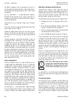
When it is time to transfer the refrigerant from the RSR
to the refrigeration unit, the latter must first be charged
with gas.
This is particularly true of refrigeration units contain-
ing liquid coolers and/or water cooled condensers. If
liquid refrigerant is charged in the unit when the unit
pressure is lower than the saturation pressure equiva-
lent to 32°F (0°C), the water tubes can freeze and burst
even though water is being pumped through the tubes.
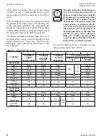
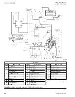
Set the water flow and valves as shown in column 4
. When the valves are set, refrig-
erant gas will flow into the refrigeration unit because
of the higher pressure in the RSR. The RSR compres-
sor does not have to run during gas charging.
When the refrigeration unit pressure is above the satu-
ration pressure equivalent to 32°F (0°C) (Table 8) or
when the pressure has equalized, close all of the valves.
On RSR Models 1100 and 1600 and on Easy Tank™
Models RT 1100 and 1600, an electric heater is in-
stalled on the bottom of the storage vessel to increase
the pressure of the stored refrigerant when the RSR is
subjected to low ambient temperatures.
Charging with Liquid Refrigerant
Set the valves and pumps as indicated in column 5 of
. Turn the toggle switch on the RSR to the
ON position.
Refrigerant vapor will be pulled off of the top of the refrig-
eration unit condenser, raised to a higher pressure by the
RSR compressor, condensed to liquid in the RSR conden ser,
and then returned to the refrigeration unit as a liquid.
The level of liquid in the storage vessel can be observed
through the sight glasses in the vessel. When the liquid has
been exhausted from the storage vessel, close valves 6 and
7 and simultaneously shut OFF the RSR toggle switch.
Removal of Refrigerant from Hoses and Storage
Vessel
Before removing the hoses between the RSR and the
refrig eration unit, open valves 1 and 3 on the manifold
and close valves 2 and 4. Start the RSR compressor and
open valve 7 simultaneously. Valve 5 should be open
and valve 6 closed.
Run the RSR compressor until a vacuum of at least
29 in. Hg. exists in the storage vessel. At this point,
close valve 7 and simultaneously move the RSR toggle
switch to the OFF position. Close manifold valves 1, 2,
3, and 4, as well as valve 5. The hose valves can then
be closed and the hoses removed from the refrigeration
unit.
TABLE 9 -
VAPOR PRESSURE – CFC-11, CFC-12,
CFC-22 AND CFC-500
TEMP.
(°F)
VAPOR PRESSURE*
CFC-11 CFC-12 CFC-22 CFC-500
-150
29.9
29.6
29.4
-140
29.9
29.4
29.0
-130
29.9
29.1
28.4
-120
29.9
28.6
27.7
-110
29.8
28.0
26.5
-100
29.8
27.0
25.0
26.4
-90
29.7
25.7
23.0
24.9
-80
29.6
24.1
20.2
22.9
-70
29.4
21.8
16.6
20.3
-60
29.2
19.0
12.0
17.0
-50
28.9
15.4
6.2
12.8
-40
28.4
11.0
0.5
7.6
-35
28.1
8.4
2.6
4.6
-30
27.8
5.4
4.9
1.2
-25
27.4
2.3
7.4
1.2
-20
27.0
0.6
10.2
3.2
-15
26.5
2.4
13.2
5.4
-10
26.0
4.4
16.4
7.8
-5
25.4
6.7
20.1
10.4
0
24.7
9.2
24.0
13.3
Содержание YORK EASYTANK LD17584
Страница 4: ...JOHNSON CONTROLS 4 FORM 50 40 OM1 713 ISSUE DATE 07 17 2013 THIS PAGE INTENTIONALLY LEFT BLANK ...
Страница 28: ...JOHNSON CONTROLS 28 FORM 50 40 OM1 713 ISSUE DATE 07 17 2013 THIS PAGE INTENTIONALLY LEFT BLANK ...
Страница 48: ...JOHNSON CONTROLS 48 FORM 50 40 OM1 713 ISSUE DATE 07 17 2013 LD17572 Figure 16 COMPRESSOR PARTS 51VSM ...


