background image

3

FORM 145.13-NO2 

ISSUE DATE: 1/22/2020

CHANGEABILITY OF THIS DOCUMENT

In complying with policy for continuous product im-

provement, the information contained in this document 

is subject to change without notice. There is no com-

mitment to update or provide current information au-

tomatically to the manual or product owner. Updated 

manuals, if applicable, can be obtained by contacting 

the nearest Service office or accessing the Offerings 

Catalog through 

www.hvacnavigator.com

.

It is the responsibility of rigging, lifting, and operating/ 

service personnel to verify the applicability of these 

documents to the equipment. If there is any question 

regarding the applicability of these documents, rig-

ging, lifting, and operating/service personnel should 

verify whether the equipment has been modified and 

if current literature is available from the owner of 

the equipment prior to performing any work on the 

equipment.

CHANGE BARS

Revisions made to this document are indicated with a 

line along the left or right hand column in the area the 

revision was made. These revisions are to technical in-

formation and any other changes in spelling, grammar 

or formatting are not included.

ASSOCIATED LITERATURE

TECHNICAL SUPPORT

If Technical Support is required, contact the Product 

Technical Support team at 877-329-7430 or 

Applied-

[email protected]

.

REPLACEMENT PARTS

For replacement parts, contact your local Source1 

Dealer.
Source1 Parts Phone Number: 800-536-6112
Source 1 Parts Website: 

http://www.source1parts.com

MANUAL DESCRIPTION

FORM NUMBER

DSV060C-300C Air-Cooled Self-Contained Installation, Operation, Maintenance

145.29-IOM3

DSH024C-120C Air-Cooled Self-Contained Installation, Operation, Maintenance

145.32-IOM5

Содержание VFD Series

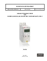
Страница 1: ...R 410A VARIABLE FREQUENCY DRIVE FOR D SERIES DSV DSH AIR COOLED SELF CONTAINED UNITS GEN C Issue Date January 22 2020 INDOOR PACKAGED EQUIPMENT INSTALLATION OPERATION NEW RELEASE Form 145 13 NO2 120...

Страница 2: ...ent and any referenced materials This in dividual shall also be familiar with and comply with all applicable industry and governmental standards and regulations pertaining to the task in question SAFE...

Страница 3: ...whether the equipment has been modified and if current literature is available from the owner of the equipment prior to performing any work on the equipment CHANGE BARS Revisions made to this documen...

Страница 4: ...0 HP Motor 237HE 5 0 HP Motor 238HE 7 5 HP Motor 239HE 10 0 HP Motor 1 2 3 4 5 6 7 8 9 10 11 12 13 VFD LAC 234HE 2 A Product Category VFD VFD Program Parameter Set VFD Option LAC Low Ambient Condense...

Страница 5: ...lle Cover 10 FIGURE 7 Input Output Diagram 11 FIGURE 8 Evaporator VFD Low Voltage Wiring Schematic With Optional VAV Sensor 208 230 460V 16 FIGURE 9 Evaporator VFD Low Voltage Wiring Schematic 575v 17...

Страница 6: ...6 FORM 145 13 NO2 ISSUE DATE 1 22 2020 THIS PAGE INTENTIONALLY LEFT BLANK...

Страница 7: ...oss 24VAC and 24VDC wiring on EVFDR relay SECTION 1 INSTALLATION Do not enter Setup mode when powering on the VFD Do not change parameters 4009 and 4011 for the VAV option on DSH DSV C gen units For t...

Страница 8: ...units The transducer is supplied with two 1 4 inch OD pres sure fittings and accepts field provided 1 4 inch push on tubing for lengths of up to 300 feet The positive HIGH and negative LOW pressure p...

Страница 9: ...ts and the 8 ton DSH unit with 3 refrigeration stages the evaporator fan is set to run at 50 60 and 100 speed The 2 5 ton DSH units and 5 ton DSV unit do not have a VFD as a standard and operate at si...

Страница 10: ...e in the supply duct as required run 1 4 inch push on tube to the corner post opening and connect to the positive HIGH side fit ting LD20863 Figure 5 CONNECTING NEGATIVE AND POSITIVE SIDE FITTINGS Che...

Страница 11: ...DC for DSH DSV C gen DISPLAY In AUTO MODE the following parameters display on control display 1 30 60Hz is the output frequency to the motor The minimum factory set frequency allowed is 30 Hz 2 0 0 No...

Страница 12: ...REF1 MIN 0 Hz 05 REF1 MAX 60 Hz 06 REF2 SELECT AI1 07 REF2 MIN 0 08 REF2 MAX 100 13 ANALOGUE INPUTS 01 MINIMUM AI1 20 02 MAXIMUM AI1 100 14 RELAY OUTPUTS 01 RELAY OUTPUT 1 FLT ALARM 16 SYSTEM CONTROL...

Страница 13: ...VE DEPENDENT A 07 MOTOR NOM FREQ 60 Hz 08 MOTOR NOM SPEED DRIVE DEPENDENT rpm 09 MOTOR NOM POWER DRIVE DEPENDENT hp 10 START STOP DIR 01 EXT1 COMMANDS NOT SEL 02 EXT2 COMMANDS DI1 03 DIRECTION FORWARD...

Страница 14: ...ACTORY PARAMETERS AND SIGNALS FOR 575V EVAPORATOR SETTINGS ABB ACS250 NAME VALUE UNIT 99 START UP DATA 02 APPLIC MACRO 1 05 MOTOR NOM VOLT DRIVE DEPENDENT V 06 MOTOR NOM CURR DRIVE DEPENDENT A 07 MOTO...

Страница 15: ...460 3 60 9 70 VFD LAC 239HE 2 208 230 3 60 10 00 26 00 1770 VFD LAC 239HE 4 460 3 60 12 50 VFD SEC 233HE 2 208 230 3 60 1 00 3 10 1760 VFD SEC 233HE 4 460 3 60 1 50 VFD SEC 233HE 5 575 3 60 1 20 VFD...

Страница 16: ...16 FORM 145 13 NO2 ISSUE DATE 1 22 2020 SECTION 2 Operation VFD OPTION SCHEMATICS LD28643 Figure 8 EVAPORATOR VFD LOW VOLTAGE WIRING SCHEMATIC WITH OPTIONAL VAV SENSOR 208 230 460V...

Страница 17: ...ION 2 Operation FORM 145 13 NO2 ISSUE DATE 1 22 2020 LD28648 Figure 9 EVAPORATOR VFD LOW VOLTAGE WIRING SCHEMATIC 575V LD28644 Figure 10 EVAPORATOR HIGH VOLTAGE POWER SCHEMATIC FOR ALL UNITS 208 230 4...

Страница 18: ...ISSUE DATE 1 22 2020 SECTION 2 Operation LD28647 Figure 11 CONDENSER VFD LOW VOLTAGE WIRING SCHEMATIC 208 230 460V LD28646 Figure 12 CONDENSER VFD HIGH VOLTAGE WIRING SCHEMATIC WITH OPTIONAL MANUAL B...

Страница 19: ...19 SECTION 2 Operation FORM 145 13 NO2 ISSUE DATE 1 22 2020 THIS PAGE INTENTIONALLY LEFT BLANK...

Страница 20: ...9 www johnsoncontrols com Subject to change without notice Form 145 13 NO2 120 New Release All rights reserved The Smart Equipment logo is a trademark of Johnson Controls in the United States and othe...

Отзывы: