


1083286-UIM-L-1219
Johnson Controls Ducted Systems
15
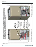
Twinning Instructions
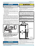
Connect the control wiring as shown in Figure 17.
1. Connect the low voltage wiring from the wall thermostat to the termi-
nal strip on the control board of Furnace #1.
2.
Connect a wire from the TWIN terminal of Furnace #1 to the TWIN
terminal of Furnace #2.
3.
Install a separate 24V relay as shown in the diagram below. Use of
this relay is required, as it ensures that the transformers of the two
furnaces are isolated, thus preventing the possibility of any safety
devices being bypassed.
4.
Connect the 24V common wires of furnace #1 to the 24V common
terminal of furnace #2.
Twinning Operation
Heating - On a call for heat (W signal) from the wall thermostat, both
furnaces will start the ignition sequence and the burners on both fur-
naces will light. About thirty seconds after the burners light, the blowers
on both furnaces will come on in heating speed. When the thermostat is
satisfied, the burners will all shut off and, after the selected blower off
delay time, both blowers will shut off at the same time. The twinning
control ensures that both blowers come on and shut off at the same
time.
Cooling - On a call for cooling (Y signal) from the wall thermostat, both
furnace blowers will come on at the same time in cooling speed. When
the thermostat is satisfied, both blowers will stay on for 60 seconds,
then will shut off at the same time.
Continuous Fan - On a thermostat call for continuous fan (G signal),
both furnace blowers will come on at the same time in cooling speed
and will stay on until the G signal is removed.
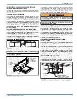
SECTION VII: CONDENSATE PIPING AND
FURNACE VENTING CONFIGURATION
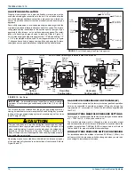
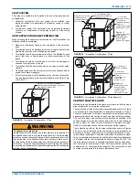
CONDENSATE DRAIN LOCATION
As shipped from the factory:
• For all 040, 060, & 080K input furnaces the main drain is plumbed
through the casing right-side opening when viewed from the front
of the furnace.
• For all 100, 120, & 130K input furnaces the main drain is plumbed
through the casing left-side opening when viewed from the front of
the furnace.
The condensate hoses must slope downwards at all points.
When drain hose routing changes are required (shown in Figures 19 -
22), be sure to cap all un-used openings.
If rerouting hoses - excess length should be cut off so that no sagging
loops will collect and hold condensate - which will cause the furnace to
not operate.
No hose clamps are needed for connecting to the condensate pan.
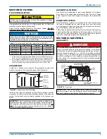
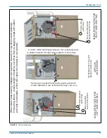
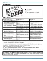
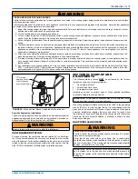
The condensate will flow to the drain better if an open stand pipe is
installed in the drain line. See Figure 18.
Do not drain other devices (humidifier, indoor coil, etc.) into the top
opening of the vent stand pipe. Instead, install a second tee in the
vented drain tube below the furnace drain tee and route additional
drainage through the new tee.
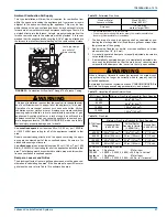
NOTICE
Furnace control boards must be set up the same. Confirm that the
staging jumper is on the same setting. Confirm that the blower motors
are connected to the same speed taps.
FIGURE 17:
Twinning Wiring Diagram
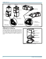
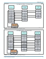
NOTICE
The Figures 19 - 22 show the condensate drain arrangement for the
various possible furnace and vent blower positions.
W
G
C
R
Y
TWIN
TO A/C
WALL THERMOSTAT
W
G
R
Y
ISOLATION
RELAY
FURNACE 2
CONTROL BOARD
W
G
C
R
Y
TWIN
FURNACE 1
CONTROL BOARD
CAUTION
The furnace condensate pan is self priming and contains an internal
trap to prevent flue gas leaking. Do not install an external condensate
trap.
IMPORTANT:
The furnace, indoor coil, and humidifier drains may be
combined and drained together. The indoor coil drain may have an
external, field-supplied trap prior to the furnace drain connection to
prevent conditioned air leakage. All drain connections (furnace,
indoor coil, or humidifier) must be terminated into an open or vented
drain as close to the respective equipment as possible. Regular main-
tenance is required on condensate drainage system.
IMPORTANT:
Condensate must be disposed of properly. Follow
local plumbing
or wastewater codes. The drain line must maintain a 1/4” per foot (20
mm/m) downward slope to the drain.
IMPORTANT:
If an external vent tee is being installed, then it must
have its own condensate trap before it is disposed into an open or
vented drain.
This is not to be considered as a second trap as ref-
erenced elsewhere in this document.
FIGURE 18:
Typical Condensate Drain, Vertical Installation
!
23(167$1'3,3(
$QWLVLSKRQDLUYHQW
7223(125
9(17(''5$,1
7((
$
´0D[


