CCS Smart Equipment Control Board for Single Packaged Unit (SPU) Controller Installation Instructions
2
In certain cases, you may need to share a 24 V
transformer with multiple CCS devices. Be sure that
you maintain cons, -, and common wiring
terminations on the shared CCS devices.
Setup and Adjustments
To quickly set up your CCS network:
1.
On each end of the 3-conductor cable, strip the
outside insulation back approximately 2 in.
(51 mm).
2.
Tear off excess foil shield, leaving the bare drain
wire and the three insulated conductors.
3.
On each end of the three insulated conductors in
the cable, strip the insulation back approximately
1/8 to 1/4 in. (4 to 7 mm).
4.
Choose a color pattern to follow and insert each of
the three conductors into one each of the three
terminals on the CCS board communication
connector.
5.
Tighten each terminal until the wire is secure.
6.
Ground the drain wire at one end only of the
communication trunk. Do this on the last unit in
line.
Use an existing hole or drill a hole and insert a
sheet metal screw in the back plate below the
communication connector.
Wrap the bare drain wire around the screw and
tighten the screw. This is the only location where
the shield is grounded.
7.
Daisy chain the three-conductor wire between the
remaining SPUs. Connect the drain wires together
with the wire nuts. Follow the stripping and
connecting procedure in Step 1 through Step .
8.
Run the cable from the last unit to the location of
the System Manager or Zone Coordinator. Follow
the connection instructions for the System Manger
or Zone Coordinator. Figure 4 displays an example
communication riser.
9.
Make sure all the SPUs are powered and operating
properly.
Note:
Be sure you observe polarity of each of the
conductors in the communication cable.
Communication Bus
The UCB default address is set to 4. The available
values range from 0 to 127. To view the UCB Network
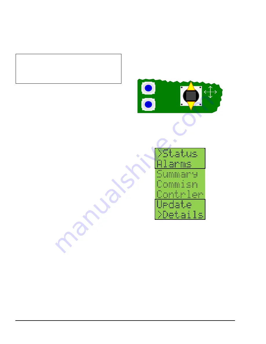
Address, use the joystick and the two push buttons
below the LCD, to navigate through the menus to the
Commissioning menu (Figure 1).
Up and down movements of the joystick move the >
cursor and scroll through the selections in the active
section of the menu (Figure 2).
Each menu selection represents either a submenu or a
property. Press Enter to display the items in the
submenu or the values of the selected property.
Once you navigate to the Commissioning menu, use
the cursor to scroll to the Network submenu. From the
Address submenu, press Enter to display the current
network address. Move up or down with the joystick to
display the values of other properties.
IMPORTANT:
Do not inter, -, and
common 24 V terminations when sharing a
transformer with multiple CCS devices.
Interchanging these terminations can cause damage
to the controller.
Figure 1: Joystick and Push Buttons on UCB
ENTER
CANCEL
JOY
Figure 2: UCB Top Level Menu


