background image

Engineering manual - SAB 193-233-283 S A-frame (including ATEX)
008831 en 2020.10

79/168

Physical and connection data

Approx.

dimensions

SGC

1913

SGC

1918

SGC

2313

SGC

2317

SGC

2321

SGC

2813

SGC

2817

SGC

2821

SGC

2824

SAB

193 S

SAB

193 L

SAB

233 S

SAB

233 L

SAB

233 E

SAB

283 S

SAB

283 L

SAB

283 E

SAB

283 X

J

mm

(In.)

101.6

(4.00)

152.4

(6.00)

203.2

(8.00)

K

mm

(In.)

75.7

(2.98)

91.4

(3.60)

111.0

(4.37)

L

mm

(In.)

290.1

(11.42)

326.9

(12.87)

387.3

(15.25)

M

mm

(In.)

57.2

(2.25)

63.5

(2.50)

82.6

(3.25)

N

mm

(In.)

95.3

(3.75)

96.8

(3.81)

127.0

(5.00)

O

mm

(In.)

12.7

(0.50)

15.9

(0.63)

22.2

(0.88)

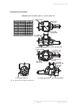
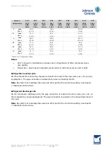
Table 14: Dimensional outline

Notes:

2817 is shown for illustrative purposes only. Configurations of other compressor sizes
vary slightly.

Model 19xx - 28xx has an integrated suction strainer with side access on left or right.

Refrigeration suction side

On the compressor suction side, the pipe connection is made to the stop valve, pos. 101, see pip-
ing diagrams. The pipe connection is welded on the valve connecting branch.

Note:

Be careful not to damage the valve and other parts of the unit when welding. See chapter

7. Installation instructions

.

Refrigerant discharge side

On the compressor discharge side, the pipe connection is made to the stop valve, pos. 102, on
the oil separator, see piping diagrams. The pipe connection is welded on the connecting branch of
the valve.

Note:

Be careful not to damage the valve and other parts of the unit when welding. See chapter

7. Installation instructions

.

Содержание Sabroe SAB 193 L

Страница 1: ...SAB 193 233 283 S A frame including ATEX Screw compressor units Engineering manual en ...

Страница 2: ......

Страница 3: ...frigerant cooled oil cooler Water cooled oil cooler No oil cooler Liquid injection in compressor Single port Dual port Discharge port Standard AC Low Vi port Oil pump Economiser system ECO system Economiser connection Economiser type _________ Ex execution ATEX T3 T4 Other _________ Supply voltage Motor 3 x _________V _________ Hz Control 1 x _________V ________ Hz Heating elements phasing 1 x ___...

Страница 4: ...ne accord ing to EN 13136 Vessel data Type External surface m2 Design pressure bar Condenser Evaporator Liquid separator Oil separator Oil cooler Economiser Other Pressure loss if any from safety valve to customer connection based on design pressure bar _____________ Safety valve type Back pressure dependent Back pressure independent ...

Страница 5: ...roof equipment 17 2 6 Vessel name plate 18 2 7 Unit pipe system name plate 19 2 8 Signs 21 3 Safety precautions 22 3 1 Areas of application 22 3 1 1 Application of the screw compressor 22 3 1 2 Application of combustion engines 22 3 2 Safety precautions 23 3 2 1 General precautions 23 3 2 2 Work area safety 23 3 2 3 During operation 23 3 2 4 Safety during maintenance and service 24 3 2 5 Electrica...

Страница 6: ...oil filter 46 4 16 Compressor hydraulic system 46 4 17 Compressor oil cooling systems 48 4 18 Suction check valve by pass 49 4 19 Requirements for ambient temperatures and humidity 51 4 20 Oil carry over to plant 52 4 21 Selecting lubricating oil for Sabroe screw compressors 53 4 22 Oil charge 53 4 23 Heating rod element for oil heating pos 30 53 4 24 Oil level switch 54 4 25 Cold start system 54 ...

Страница 7: ...Selecting electric motor 92 6 7 Motor dimension 92 6 8 Motor selection and starting torque 93 6 9 Motor compressor torque 94 6 10 Direction of rotation 95 6 11 Emergency stop 95 6 12 Other emergency stop requirements 95 6 13 Noise data 96 6 14 Noise data for SAB 193 233 283 96 6 15 Vibrations and test pressure levels 97 6 15 1 Vibration data for compressors all compressor types 97 6 15 2 Test pres...

Страница 8: ...tly on the foundation 106 7 22 Mass damping between unit and building 107 7 23 Damping using vibration dampers 107 7 24 VSD equipment 110 7 25 Calculation of centre of gravity support reactions and tipping angle 112 7 26 Instruction for mounting of coupling 120 7 27 BPU coupling installation procedure 121 7 28 Piping connections 123 7 29 Connecting electricity supply 124 7 30 Pressure testing 125 ...

Страница 9: ...45 13 Service instructions 150 14 Transport instructions 151 14 1 Safety precautions 151 14 2 Transport data 152 14 3 Personnel requirements 152 14 4 Handling of compressor and unit 152 14 5 Loading instructions 153 14 6 Preparations before lifting 153 14 7 Loading 153 14 8 Transport instructions 154 14 9 Transport regulations 154 14 10 Unpacking and inspecting the unit 154 14 11 Moving the equipm...

Страница 10: ... SAB 193 233 283 S A frame including ATEX 10 168 008831 en 2020 10 16 Spare parts list 160 17 Spare parts drawings 161 18 Final disposal 162 18 1 Safety precautions 162 18 2 Waste disposal 162 19 Appendices 163 Index 164 ...

Страница 11: ...ual is primarily intended for sales service and contracting purposes All compressor intervention within the warranty period must be performed by competent person nel only If not the warranty no longer applies 1 3 Compressor name Sabroe Frick The compressor in a Sabroe SAB 193 233 and 283 screw compressor unit is manufactured by Frick Below is indicated how the Sabroe and Frick compressor names are...

Страница 12: ...ns chapter has been revised Various minor corrections and changes 2018 03 Version 3 Name plates with EurAsian Conformity mark EAC have been added Requirements for competent persons section has been added F gas regulation section has been updated Noise data Add 2 dBA to the values for 60 Hz compressors used to be 3 The unsigned declaration of conformity has been removed It can be found in the opera...

Страница 13: ...ipment and or minor injury Note Indicates an operating procedure practice or portion thereof which is essential to highlight 1 7 Requirements for competent persons Personnel working on the unit must be competent in accordance with national safety rules and regulations relating to flammable refrigerants or according to EN 13313 Maintenance work must be performed according to EN 378 or ISO 5149 supp...

Страница 14: ...nson Controls Denmark 2 1 Main users Information concerning Signs and warnings is intended for all users The following describes the importance of the individual signs attached to the Johnson Controls Denmark products Before a compressor unit is put into operation it must be fitted with the warning signs belonging to the type of compressor unit in accordance with the rules and regulations in force...

Страница 15: ...40A90000015Z Plant Decade Month Year Global seq no Additional remarks 1024 0 A 9 0000015 Z Month A JAN B FEB C MAR D APR E MAY F JUN G JUL H AUG K SEP L OCT M NOV N DEC Additional remarks R Remanufactured Z Deviation from standard configuration The compressor name plate contains this information Model no Manufacturer type designation Part no Manufacturer part number Serial no Compressor manufactur...

Страница 16: ...ATEX compressor The ATEX compressor name plate contains this information Model no Manufacturer type designation Part no Manufacturer part number Serial no Compressor manufacturing number Max driver speed rpm Maximum number of revolutions allowed Max allowable pressure psig bar Maximum working pressure of compressor psig bar Assembled in Manufacturing country ...

Страница 17: ... use in areas with possible occurrence of ex plosive gasses G Hazardous environment G indicates that the equipment is suitable for use in potentially explosive gas vapour and fog atmospheres T3 T4 Temperature class indicates the surface temperatures that may occur on the compressor Warning On ATEX executions the limits in Table 2 must always be respected Temp class Max surface temp Max temperature...

Страница 18: ...evant 3rd party notified body For EC PED approval CAT Category 1 2 3 or 4 according to the PED directive Side For heat exchangers only Refers to the columns Shell side and Tube side Fluid Designation of the primary refrigerant s and the secondary re frigerant s For EC PED approval Designation of the refrigerant s and or the highest fluid group Group 1 or 2 according to the PED directive Allowable ...

Страница 19: ...voltage Test pressure Allowable pressure Category Pressure system Refrigerant charge Max Allowable temp Min Max Refrigeration unit No Type Year Fluid Group Control V Hz kg bar g bar g C LP side HP side Johnson Controls Denmark ApS Christian X s Vej 201 8270 Højbjerg Denmark www sabroe com 2516 343 Main Fig 7 Name plate for ATEX unit Установка холодильная Назначение Код стандарта сертификата Хладаг...

Страница 20: ...ressure system The low pressure side of the unit piping system is referred to as the LP side The high pressure side of the unit piping system is referred to as the HP side Category For EC PED approval The maximum category of the piping system CAT 1 2 or 3 or of the assembly unit and piping CAT 3 or 4 Allowable pressure max The max pressure pressure relative to atmospheric pressure that the unit pi...

Страница 21: ...ressor blocks and units are usu ally delivered without refrigerant and oil To protect the compressors against internal corrosion they are delivered evacuated of all atmospheric air and charged with dry Nitrogen N2 to an overpressure of 0 5 bar 7 3 PSI In such cases a yellow sign is affixed to a visible spot on the compressor The magnetic field on the rotor may affect pacemakers The motor rotor con...

Страница 22: ...ative humidity RH may exceed 90 Johnson Controls Denmark further accept no liability of any kind for damage to compres sor unit and plant parts caused by torsional oscillation or the like which is attributable to built in VSD solutions initiated by the customer after delivery ATEX The compressor is approved for application in potentially explosive atmospheres provided it is fitted with explosion p...

Страница 23: ...tection when operating the compressor unit Use safety equipment Wear appropriate gloves as well as eye and face protection when working with parts containing refrigerant and or lubricating oil Use proper electrical safety protection Note These instructions only provide general information The owner of the refrigeration plant is responsible for ensuring that all codes regulations and industry stand...

Страница 24: ...ted with an effective biological treatment programme 3 2 4 Safety during maintenance and service Personnel must be competent according to national safety rules and regulations and per form the maintenance work according to EN 378 Read chapter 3 Safety precautions before opening the compressor and other parts of the refrigeration plant It is recommended to remove all main fuses Switch off all elect...

Страница 25: ...ust also be in conformity with the ATEX directive For equipment not supplied by Johnson Controls Denmark it is the contractor who is responsible for ensuring that the equipment is in conformity with the ATEX directive Specifically the contractor is responsible for equalising potential differences on the compressor 3 2 6 Power supply Danger The voltage used in the drive can cause severe electric sh...

Страница 26: ... Be aware that large amounts of leaking or released refrigerant entail a risk of asphyxiation If in direct contact with leaking liquid refrigerant there is a high risk of injuries caused by frostbite 3 2 9 Purging a refrigeration plant Purging of air or other non condensable gases is required in order to keep high system perform ance and avoid corrosion of the equipment which could endanger the sa...

Страница 27: ...r 2020 Existing systems can be serviced with reclaimed refrigerant until 2030 provided that proper quality refrigerant is available Read the local regulations Labelling The unit must be fitted with a label name plate Refrigerant type charge in kg and CO2Equiva lent CO2eq must be stated on the plate Leakage test It is the operator s responsibility to ensure that the unit is checked for leakages by ...

Страница 28: ...d training programs for personnel involved in leakage inspections and the recovery recycling reclamation and destruction of fluorinated gases Record keeping For all units containing fluorinated greenhouse gases in quantities of more than 5 tonnes of CO2eq records must be kept indicating the quantity and type of product quantities added for re charges and the quantity recovered during servicing mai...

Страница 29: ...near all bulk installations with ammonia When applying first aid the persons assisting must be duly protected to avoid further injuries First aid measures Inhalation Immediately move affected personnel into fresh air and loosen clothing restricting breathing Call a doctor ambulance with oxygen equipment Keep the patient still and warmly wrapped in blankets Do not in any way attempt to provoke vomi...

Страница 30: ...fected persons are moved from low lying or poorly ventilated rooms where high gas con centrations are suspected the rescuer must wear a lifeline and be under constant observation from an assistant outside the room Do not use adrenaline or similar heart stimuli Inhalation Immediately move affected persons into fresh air Keep them still and warm and loosen clothing restricting breathing If the patie...

Страница 31: ... inhaled they will attack the human nervous system When halogenated gases come into contact with open flame or hot surfaces over approximately 300 C they will decompose to produce poisonous chemicals These have a very pungent odour and will therefore warn personnel of their presence At high concentrations R717 causes respiratory problems When the amount of ammonia vapour in air is between 15 and 2...

Страница 32: ...Carbon dioxide CO2 Carbon dioxide CO2 is a greenhouse gas with a GWP Global Warming Potential factor of 1 It is found in the atmosphere in a concentration of 0 036 vol 360 parts per mil lion ppm As CO2 is extracted from atmospheric air it can safely be released into the at mosphere and does not contribute to enhancing the greenhouse effect At atmospheric pressure solid CO2 dry ice at the temperatu...

Страница 33: ...en charging or purging a refrigeration plant Never empty brines down a sewer or into the environment The brine must be collected in suitable containers clearly marked with the contents and sent to an approved incineration plant Note These instructions only provide general information The owner of the refrigeration plant is responsible for ensuring that all codes regulations and industry standards ...

Страница 34: ...n the operating conditions Fig 9 SAB 193 front Fig 10 SAB 193 back SAB 193 on oil separator OHU 04123 shown Design Construction A description of the components which form part of the unit is given below More detailed descrip tions are included in separate documents for the individual components The compressor CS the electric motor M and the oil separator OS are mounted on a base frame The base fra...

Страница 35: ...echnical data contains a list of tables of the screw compressors indicating weight di mensions and geometric swept volume among other things The compressor type is stated on the name plate shown in Fig 13 and all compressors are equip ped with such a name plate See details in chapter 2 Signs and warnings The serial number of each compressor is stamped into the compressor block Fig 13 Compressor na...

Страница 36: ... this direction will cause problems with the oil separator in terms of oil level shutdown for instance The requirements are stated in Table 4 Fig 14 Front of unit athwartships Fig 15 Side of unit fore and aft Athwartships Fore and aft direction Axial rotation around motor compressor shaft axis Transversal rotation around axis perpendicular to motor compressor shaft Static Dynamic Static Dynamic 15...

Страница 37: ...rew compressors meaning the same UniSAB III unit is used for both compressor types Once compressor type refrigerant and a few other functions have been se lected UniSAB III is ready for operation UniSAB III is based on Johnson Controls Denmark s ex tensive experience with design and operation of compressor control systems Fig 16 UniSAB III UniSAB III is designed for safe control monitoring and opt...

Страница 38: ...ressors For correct fault diagnosis in case of compressor shutdown UniSAB III immediately stores all shutdown situations in its memory which can be displayed and analysed on the display at any time Instrumentation Depending on the compressor type UniSAB III is equipped with a number of pressure and tem perature transducers as well as position transmitters on the compressor Screw compressors are fi...

Страница 39: ... to the compressor and does not reflect the design pressure of the various system components 8 All bearing and control oil vented to closed thread in the compressor instead of suction port to avoid performance penalties from superheating suction gas 9 Shaft seal design to maintain operating pressure on seal well below discharge pressure for increased seal life 10 Oil injected into the rotors to ma...

Страница 40: ...lly actuate the slide valve and slide stop It provides oil pressure to the balance pistons to increase bearing life It provides an oil seal between the rotors to prevent rotor contact or gas bypassing The compressor unit may be equipped with either a no pump or a demand pump lubrication system Additionally either system may contain Dual oil filters and liquid injection Water cooled or thermosyphon...

Страница 41: ...ifferential pressure between the compressor dis charge and the main oil injection port If this differential pressure is less than 2 5 bar 35 psi the demand pump will turn on and continue to run until obtaining a 3 bar 45 psi differential pressure Note For alarm descriptions and shutdown or cut out parameters see separate control system manual 4 11 Flow security To ensure compressor lubrication bef...

Страница 42: ...t the bottom In the oil separator the oil is separated from the discharge gas and taken to the oil reservoir Both vessels are firmly connected to pipes which cannot be separated Oil separator As illustrated in Fig 20 and Fig 21 the discharge gas and the oil from the compressor first pass the demisters where the main part of the oil is separated from the discharge gas and drained into the oil vesse...

Страница 43: ...ents two oil return pipes will be fitted on the unit See piping diagram The oil separator is fitted with an automatic oil return valve see subsection 4 13 Oil vessel As already mentioned the lubricating oil is collected in the oil vessel The oil level in the vessel must always be visible in the sight glasses pos 31 The correct amount of oil in the unit is stated in Table 50 Table 51 and Table 52 i...

Страница 44: ...quently the pressure loss of the gas flow through the nozzle pos 7 is unable to move the piston pos 7 However the pressure loss of the oil flow through the nozzle pos 7 is able to move the piston pos 7 Thus the spring force pos 9 is equalised and a transverse bore pos 10 with a considerably larger bore than pos 7 will open Because the bore is larger oil collections at the oil return valve inlet ca...

Страница 45: ...e filter cartridges depending on compressor size Fig 24 External oil filter The filter is a horizontal filter through which the oil must pass the filter cartridge from the outside in This way dirt will accumulate outside the filter cartridge and the filter housing must therefore be cleaned when the filter cartridge is replaced The filter is protected against bursting because UniSAB III will stop t...

Страница 46: ... V1 V2 SC1 SC3 and SC4 are always open Single acting mode high stage TC 15 C Close the valve at SC2 Open the valve at BP by pass High stage compressor loading The compressor loads when the MSV solenoid valve YY2 is energised and oil flows from the un loading side of the cylinder out of the port SC1 through the valve ports A and T to the compres sor suction side Simultaneously the discharge pressur...

Страница 47: ...n the MSS solenoid valve YY3 is energised and oil flows from the oil manifold through the valve ports P and A to the compressor port SC3 enters the increase side of the cylinder and overcomes the decrease spring tension The inboard side of the slide stop piston is at suction pressure Compressor Vi decrease The volume ratio Vi is decreased when the MSS solenoid valve YY4 is energised which permits ...

Страница 48: ...7 and Fig 28 Dual port liquid injection The dual port liquid injection system is designed to obtain the most efficient compressor perform ance at high and low compression ratios by permitting injection of liquid refrigerant into one of two ports optimally located on the compressor This minimises the performance penalty incurred with liquid injection oil cooling The dual port system contains all th...

Страница 49: ...tor to slowly bleed down to ap proximately system suction pressure when the unit is stopped having this valve cracked open al lows the compressor drive motor to have an easier start and the discharge check valve will seat more tightly If the drive coupling backspins start closing the valve until the backspin stops If the separator oil level foams excessively on shutdown NV 2 should be closed sligh...

Страница 50: ...void the possibility of back feeding to a shutdown compressor from a common economiser vessel On booster systems the check valve CV 4 should be installed with a 1 7 bar 25 psi spring to avoid the possibility of air ingress into the system if the system suction pressure is below atmospheric NV 2 must be closed if the oil pump should run for long periods of time when the compressor is stopped This i...

Страница 51: ...sor units Heating element s in the crankcase on all reciprocating compressors These heating elements are normally capable of keeping the oil temperature at least 10K above the ambient temperature Despite the above precautions however undesirable condensing is still a risk if the ambient temperature falls significantly 10 15K below the system condensing tem perature If this happens it should be mon...

Страница 52: ...ormula with good conformity to practice experience Alternatively use steam pressure from oil company Dalton s law for partial pressure of two substances in vapour form gives good conformity with practice experience Liquid oil aerosol carry over depends on oil separator oil separator challenge flow refrigerant oil type solubility pressures and temperatures 10 273 1 220 1 1 1 1270 12 Disch t Fp Fp o...

Страница 53: ...andstill period the oil re ceiver has one or two built in heating rods Before start up the heating rods must have been acti vated for six to eight hours to ensure that there is only a minimum of refrigerant in the oil When containing a lot of refrigerant the oil will lose its lubricating property and tend to foam which can cause shutdown by the level switch As illustrated in Fig 30 the direct heat...

Страница 54: ...discharge valve This valve ensures a rapid devel opment of oil pressure at initial start up in order to lubricate the compressor without requiring an oil pump even in cold ambient temperatures with all pressures equalised Warning Be extremely careful when dismantling the cold start valve on the discharge side of the unit as condensed refrigerant often is trapped between the cold start valve and th...

Страница 55: ...alve fully open for a very low operating pressure drop Booster applications For booster applications the valve is equipped with a light spring which produces 0 5 bar 7 psi oil pressure above suction pressure before it fully powers open An oil pump is required to ensure compressor lubrication The unit is also equipped with a suction check valve by pass The oil separator will slowly bleed down to ap...

Страница 56: ...main valve In the chamber above the piston pos 5 there is the same pressure P1 as under the valve cone pos 2 since the piston rod pos 3 is pierced When the main valve is closed the pressure P2 in the chamber pos 6 below the piston will be the same as the compressor discharge pressure P2 since the pressure P2 is equalised through the nozzle pos 7 If the pilot valve pos 221 opens due to too a high p...

Страница 57: ...s mounted on the unit with the oil piping connected Water connections and controls are field installed Thermosyphon oil cooling The optional thermosyphon cooler is a plate and shell design Vah terus or a plate type oil cooler AlfaNova It is designed for design pressure 28 bar on the shell side and 28 bar on the plate side The oil coolers are mounted on the unit with the oil piping con nected Refri...

Страница 58: ...ig 35 uses two dip tubes in the receiver The liquid tube is below the evaporator tube to ensure continued oil cooling when the receiver level is low Fig 35 Dual dip tube method The level control method Fig 36 uses a float level control on the receiver to close a solenoid valve feeding the evaporator when the liquid falls below the amount necessary for five minutes of liquid injection oil cooling F...

Страница 59: ...83 S L and E 1 2 106 5 48 3 1 7 48 1 SAB 283 X 3 4 146 0 65 8 2 3 65 0 Table 6 Based on 100 ft liquid line For longer runs increase line size accordingly Conditions Booster High stage Evaporating 40 C 40 F Evaporating 17 8 C 17 8 Condensing 35 C 95 F Condensing 35 C 95 F Intermediate 12 2 C 10 F 4 29 Thermosyphon oil cooling Thermosyphon oil coolers like water or glycol cooled oil coolers eliminat...

Страница 60: ...E Unit Type of cooler Inlet Outlet Type Plates Water Refri Water Refri SAB 193 S L High stage 3HH 116 66 34 DN80 DN50 DN50 DN80 DN50 DN50 DN80 DN50 DN50 DN80 DN50 DN50 SAB 193 S L Booster 3HH 34 DN50 DN50 DN50 DN50 SAB 233 S High stage 3HH 116 66 34 DN80 DN50 DN50 DN80 DN50 DN50 DN80 DN50 DN50 DN80 DN50 DN50 SAB 233 S Booster 3HH 34 DN50 DN50 DN50 DN50 SAB 233 L E High stage 3HH 146 116 66 34 DN10...

Страница 61: ...quate water connections Determine the size of the water cooled oil cooler supplied with the unit as outlined in COMP1 The water supply must be sufficient to meet the required flow Johnson Controls Denmark recommends a closed loop system for the waterside of the oil cooler Careful attention to water treatment is essential to ensure adequate life of the cooler if cooling tower water is used It is im...

Страница 62: ...ing tables Keep these values in mind when design ing your system It is also recommended to minimise connection loads when designing piping systems See Fig 38 Fig 38 AlfaNova oil cooler Fx Fy Fz F N Mx My Mz M Nm Reduction of max approved design pressure bar AlfaNova HP 52 120 25 10 Table 9 Maximum recommended load components during operation Threaded connection Fx N Fy N Fz N Mx Nm My Nm M Nm 1 1 ...

Страница 63: ...tting the response pressure using the adjusting screw and then securing the adjusting screw with the hexagon nut Fig 40 The by pass valve serves two purposes To protect against overheating by allowing overflow if the oil pressure downstream pump exceeds the setting of the pressure relief valve According to KRACHT the pump can run continuously with at least 50 by pass without overheating To protect...

Страница 64: ...nsing temperatures fluctuate into the shaded area only occasionally during the winter the demand pump avoids unnecessary consumption of pump horsepower Fig 43 Standard lubrication system limits high stage Start up The pump must only run without an oil flow for brief periods of time because of the bearings and shaft seal Service The oil pump is designed as one unit and should therefore not be disas...

Страница 65: ...ssure regulator valve is not used on a flash economiser it is possi ble that no pressure difference will exist to drive liquid from the flash vessel to the evaporators since the flash vessel pressure will approach suction pressure at a decreased slide valve position In cases where wide swings in pressure are anticipated in the flash economiser vessel it may be necessary to add an outlet pressure r...

Страница 66: ...ption The electric shutoff feature is necessary to prevent flow from the common economiser vessel to the suction side of a stopped compressor through the suction check valve bypass line if the other compressors and the common econo miser vessel are still operating and the HV2 valve on the suction bypass is open For refrigeration plants using a Packaged Refrigerant Recirculation PRR unit and a dire...

Страница 67: ...283 S A frame including ATEX 008831 en 2020 10 67 168 Technical description Fig 47 Shell and coil economiser system Fig 48 Direct expansion economiser system Fig 49 Flash economiser system Fig 50 Multiple compressor economiser system ...

Страница 68: ...manual SAB 193 233 283 S A frame including ATEX 68 168 008831 en 2020 10 Technical description 4 34 General piping diagram 4809 052_9 Fig 51 General piping diagram SAB 193 with OHU 04123 oil separator is shown here ...

Страница 69: ...Engineering manual SAB 193 233 283 S A frame including ATEX 008831 en 2020 10 69 168 Technical description 4809 054_6 Fig 52 General piping diagram SAB 233 with OHU 04136 oil separator is shown here ...

Страница 70: ...ator SV 1 Vapour injection tongue and groove PDSLL Compressor low diff pressure cut out SD 1 Coalescer bleed str trh O ring port TW 1 Thermowell PE Pressure transducer Pressure transducers indicate PI Pressure indicator PE 1 Oil pressure manifold PIC Pressure indicator controller PE 2 Oil pressure before filter PM Pump motor PE 3 Discharge pressure PS Pressure switch control PE 4 Suction pressure ...

Страница 71: ... flow Open partly Adjusted according to manual 126 Cold start discharge valve Opens automatically 127 Compressor protection valve Closed Controlled by pilot valve 128 Pilot valve for pos 127 Closed Fixed set point 129 Suction check valve 130 Change over valve 131 Safety valve oil cooler 132 Safety valve oil cooler 133 Safety valve oil cooler 135 Stop valve before oil filter Oil filter 1 Open when ...

Страница 72: ... valve Open 170 Stop valve Open 172 Stop valve Open 173 Stop valve Open 175 Stop valve Closed 181 Slide valve unload 182 Slide valve load 183 Moveable slide stop 184 Moveable slide stop 191 Compressor 192 Electric motor 193 Oil separator 194 Oil cooler 195 Oil filter 196 Oil filter 200 Stop valves oil return Open 200 Automatic oil return 208 Damper with strainer Table 11 Positions during operation...

Страница 73: ... and pressure sensors on the unit The UniSAB III control system is described in a separate manual Fig 53 and Fig 54 show the positions of sensors valves etc See also the general piping diagram in subsection 4 34 The numbers refer to the list in subsection 4 35 Key to piping diagram Fig 53 Positions of valves and components SAB 193 with OHU 04123 181 183 182 184 151 158 114 101 EC 192 107 102 200 1...

Страница 74: ...ncluding ATEX 74 168 008831 en 2020 10 Technical description Fig 54 Positions of valves and components SAB 193 with OHU 04123 155 192 124 157 127 128 136 196 138 191 146 144 PM 1 193 ZI 3 ZI 2 YY3 4 YY1 2 123 195 137 135 120 139 119 153 121 156 145 ...

Страница 75: ...flange design etc Electrical connection must be carried out so that it complies with current legislation within the area in question Electric cables must be dimensioned on the basis of the maximum power consumption of the plant The short circuit levels in the installation point must be in compliance with fig ures for the exact electrical equipment on the unit Furthermore the overcurrent protec tio...

Страница 76: ...5 25 34 34 34 1 25 25 25 25 34 34 34 1 5 50 40 40 68 54 54 2 100 70 70 136 95 95 3 250 175 175 339 237 237 4 400 200 200 542 271 271 5 425 400 400 576 542 542 6 1000 750 750 1356 1017 1017 8 1500 1000 1000 2034 1356 1356 10 1500 1200 1200 2034 1627 1627 Table 12 Allowable flange loads Noz size Nps Load lbf Load N Axial Vert Lat Axial Vert Lat P VC VL P VC VL 1 50 50 50 222 222 222 1 25 50 50 50 22...

Страница 77: ...e discs in the check valve to strike against the stop pin and eventually damage the inside of the check valve If installing an elbow near the check valve make sure that the plate is stressed evenly If the isolation valve is mounted at the compressor suction side it should be installed with flow across the cone Please design your system piping accordingly If the suction isolation valve is installed...

Страница 78: ... 1737 1 68 39 2000 6 78 76 1979 7 77 94 2078 8 81 84 2382 5 93 80 2500 9 98 46 B mm In 698 5 27 50 712 2 28 04 726 4 28 60 757 7 29 83 759 2 29 89 881 6 34 71 900 7 35 46 1346 2 35 53 C mm In 253 5 9 98 278 8 10 98 341 9 13 46 D mm In 668 0 26 30 706 1 27 80 815 8 32 12 841 2 33 12 841 2 33 12 939 8 37 00 990 5 39 00 E mm In 580 7 22 86 662 9 26 10 667 7 26 29 F mm In 125 0 4 92 211 8 8 34 156 6 6...

Страница 79: ...urposes only Configurations of other compressor sizes vary slightly Model 19xx 28xx has an integrated suction strainer with side access on left or right Refrigeration suction side On the compressor suction side the pipe connection is made to the stop valve pos 101 see pip ing diagrams The pipe connection is welded on the valve connecting branch Note Be careful not to damage the valve and other par...

Страница 80: ...AIN SE 1 ELECTRICAL CONNECTOR SC 8 CLOSED THREAD DRAIN SB 3 COMPRESSOR OIL SUPPLY SC 14 LIQUID INJECTION BLEED SC 5 INLET PRESSURE SD 1 COALESCER BLEED SM 1 MAIN OIL INJECTION COMPRESSOR PORT LOCATIONS SAB 193 S L SGC 1913 AND 1918 PORT THREAD SIZE O RING SB 3 1 12 UN 2B 980A0012K66 SC 5 9 16 18 UNF 2B 980A0012K60 SC 6 9 16 18 UNF 2B 980A0012K60 SC 8 1 12 UN 2B 980A0012K66 SC 9 9 16 18 UNF 2B 980A...

Страница 81: ...W Vi LIQUID INJECTION SV 1 VAPOR INJECTION SC 8 CLOSED THREAD DRAIN SM 1 MAIN OIL INJECTION SC 13 OIL DRAIN CYCLINDER SC 11 CLOSED THREAD DRAIN SC 9 INLET HOUSING DRAIN SC 7 SEAL WEAPAGE PORT THREAD SIZE O RING SB 3 1 12 UN 2B 980A0012K66 SC 5 9 16 18 UNF 2B 980A0012K60 SC 6 9 16 18 UNF 2B 980A0012K60 SC 8 1 12 UN 2B 980A0012K66 SC 9 9 16 18 UNF 2B 980A0012K60 SC 11 1 12 UN 2B 980A0012K69 SC 13 9 ...

Страница 82: ... 14 9 16 18 UNF 2B 980A0012K60 SD 1 1 12 UN 2B 980A0012K66 SL 1 1 12 UN 2B 980A0012K69 SL 2 1 12 UN 2B 980A0012K69 SM 1 1 12 UN 2B 980A0012K69 SC 6 DISCHARGE PRESSURE SM 1 MAIN OIL INJECTION SV 1 VAPOR INJECTION SL 1 LOW Vi LIQUID INJECTION SC 8 CLOSED THREAD DRAIN SC 7 SEAL WEAPAGE SC 9 INLET HOUSING DRAIN SC 13 OIL DRAIN CYCLINDER SL 2 HIGH Vi LIQUID INJECTION SB 3 COMPRESSOR OIL SUPPLY SE 1 ELE...

Страница 83: ... 2B 980A0012K60 SD 1 1 12 UN 2B 980A0012K66 SL 1 1 12 UN 2B 980A0012K69 SL 2 1 12 UN 2B 980A0012K69 SM 1 1 12 UN 2B 980A0012K71 COMPRESSOR PORT LOCATIONS SAB 283 E X SGC 2821 AND 2824 SC 14 LIQUID INJECTION BLEED SD 1 COALESCER BLEED SB 3 COMPRESSOR OIL SUPPLY SC 5 INLET PRESSURE SE 1 ELECTRICAL CONNECTOR 480 ONLY SV 1 VAPOR INJECTION SL 1 LOW Vi LIQUID INJECTION SM 1 MAIN OIL INJECTION SC 6 DISCH...

Страница 84: ...be controlled by a UniSAB III regulation and control system which is mounted on the unit and connected to a number of temperature and pressure sensors on the unit Fig 62 Positions of electrical connections Fig 63 Positions of electrical connections SAB 193 with OHU 04123 shown 181 183 182 184 151 158 EC 192 163 161 160 154 159 155 192 157 PM 1 ZI 3 ZI 2 YY3 4 YY1 2 153 156 ...

Страница 85: ...tch control 160 LSLL Low level shutdown 161 HTR 1 Heater 163 High level transmitter ZI2 Capacity linear transmitter slide valve ZI3 Volumizer transmitter slide stop YY 1 Solenoid valve Energise unload slide valve YY 2 Solenoid valve Energise increase volume rate YY 3 Solenoid valve Energise increase volume ratio YY 4 Solenoid valve Energise decrease volume ratio EC UniSAB III electronic computer c...

Страница 86: ...0 VAC see the Engineering Manual for UniSAB III With UniSAB III As standard units are supplied with the Johnson Controls Denmark control system UniSAB III UniSAB III is described in a separate manual which also includes a description of its general con trols and how these are connected to UniSAB III With a control system not delivered by Johnson Controls Denmark See document no 006204 Guidelines f...

Страница 87: ...rvice engineers sales personnel and prospec tive customers 6 1 Data for compressor units Fig 64 Dimension sketch See also complete dimensioned sketches of the individual compressor types and units Oil separator OHU 04123 Compressor type Width mm Length mm Height mm Max net weight kg SAB 193 OHU 04123 1475 3250 1900 2800 Table 15 Unit dimension data Oil separator OHU 04136 Compressor type 3 HH Widt...

Страница 88: ... IEC 160L 102 225 80 176 78 172 120 265 IEC 180M 190 419 173 381 98 216 100 220 135 298 IEC 180L 210 462 188 414 128 282 110 243 184 406 IEC 200M 240 529 165 364 IEC 200L 265 584 235 518 190 419 170 375 260 573 IEC 225S 309 681 205 452 290 639 IEC 225M 355 783 340 750 240 529 235 518 388 855 IEC 250S 455 1003 335 739 IEC 250M 480 1058 445 981 360 794 340 750 395 871 IEC 280S 625 1378 570 1257 460 ...

Страница 89: ...312 SGC 2821 283 2 1 1 000 3 600 0 79546 0 022512 3 985 SGC 2824 283 2 4 1 000 3 600 0 89858 0 025430 4 501 Table 20 Geometrical swept volume Compressor SAB Compressor SGC Approx weight lbs Approx weight kg SAB 193 S SGC 1913 1720 780 SAB 193 L SGC 1918 1895 860 SAB 233 S SGC 2313 2670 1210 SAB 233 L SGC 2317 2950 1340 SAB 233 E SGC 2321 3300 1500 SAB 283 S SGC 2813 4100 1860 SAB 283 L SGC 2817 44...

Страница 90: ...ometry and its operat ing conditions Typical minimum flow for each of our compressor models is listed below Table 22 represents minimum suction flow with the slide valve fully unloaded Unit Minimum flow CFM m3 h SAB 193 S 71 121 SAB 193 L 95 161 SAB 233 S 125 212 SAB 233 L 157 267 SAB 233 E 365 621 SAB 283 S 224 380 SAB 283 L 282 479 SAB 283 E 650 1104 SAB 283 X 478 812 Table 22 Minimum suction fl...

Страница 91: ...imits depend on various factors such as the specific compressor the compressor cooling method whether there is an economiser and which refrigerant is used The relevant diagram can be ob tained from the COMP1 calculation program Fig 66 Operating limits example only 40 0 20 40 60 C 5 20 80 70 60 50 40 30 20 10 20 30 60 0 10 TC TE C 5 Condensing temperature deg C Evaporating temperature deg C Oil pum...

Страница 92: ...ing factors 1 Air conditioning plant factor 1 10 2 Other refrigeration plants factor 1 15 b Consider which type of plant the compressor is going to work on The motor must be di mensioned in accordance with the following rules For plants where a high ET may be expected consequently also a higher CT in the start up phase the motor must be dimensioned to meet the high operating tem peratures Usually ...

Страница 93: ...in specific torque data for the motor used Unit Starting torque 1 multiplier Breakaway torque ft lb Breakaway torque Nm 2 3 Mass moment of inertia lb ft2 2 3 Mass moment of inertia kg m2 SAB 193 S 0 75 10 14 5 1 0 21 SAB 193 L 1 00 10 14 6 5 0 27 SAB 233 S 1 32 14 19 13 0 55 SAB 233 L 1 66 14 19 16 0 67 SAB 233 E 2 24 14 19 18 0 77 SAB 283 S 2 36 20 27 33 1 4 SAB 283 L 2 98 20 27 41 1 7 SAB 283 E ...

Страница 94: ... that will be experienced during normal starting Note Star delta and auto transformer reduced voltage motor starting methods drastically ef fect the starting torque available from motors as indicated Across the line 100 torque Auto transformer 25 64 torque Star delta 33 torque Fig 70 Motor compressor torque 136 122 108 95 81 68 54 41 27 14 100 90 80 70 60 50 40 30 20 10 0 Nm Ft lb 50 100 75 Discha...

Страница 95: ... on the unit The emergency device must be adjusted in such a way that after a stop instruction it stays in its stop position until it is deliberately reset It must not be possible to block the emergency stop without a stop instruction being released It should only be possible to reset the emergency stop by a deliberate act Resetting the emer gency stop must not cause the compressor to start operat...

Страница 96: ...AB 193 L 104 84 SAB 233 S 105 86 SAB 233 L 106 86 SAB 233 E 107 86 SAB 283 S 106 88 SAB 283 L 107 88 SAB 283 E 108 88 SAB 283 X 108 88 Table 24 Noise data Noise data for other operating conditions can be provided by Johnson Controls Denmark on request Note The actual SPL value on site will be between the stated SPL and SWL depending on the acoustic environment in the machine room In a typical mach...

Страница 97: ...III Based on the design and decades of experience with it the evalu ation criteria given for measured values belonging to Zone II is deemed as acceptable for rms values up to 11 2 mm s Measured values above 11 2 mm s are subject to the stated actions given by the VDI 3836 Zone II III classification The measurements are made as illustrated in the figure below points A D Fig 73 Vibration data Pay at...

Страница 98: ...quirements the compressor runs at an incorrect Vi ratio screw compressors only the piping connections have been executed in a way that makes them force pull or push powers on the compressor unit or transfer vibrations to the unit caused by natural vibrations or connected machinery the vibration dampers have not been fitted or loaded correctly as indicated in the foundation drawing accompanying the...

Страница 99: ...r Sabroe compressors at an additional price Please contact your local sales representative for further information When pressure testing compressors and vessels components must first prove their strength by resisting the test pressure of the strength test This test is carried out with air Afterwards the leak test is carried out also with air at the prescribed pressure for 30 minutes Units consist ...

Страница 100: ...y with safety precautions may cause death or injury to personnel It may also cause damage to or destruction of the equipment 7 3 Installation data The physical data of the compressor is included in chapter 5 Physical and connection data See also subsection 6 13 Noise data 7 4 Installation and first start up procedure Installation in terms of mechanical work refrigeration system and piping electric...

Страница 101: ...es and materials necessary to perform the installation correctly Ordinary hand tools Tools for installing pipes including welding tool The following can be ordered Tools for alignment of coupling Tools for shaft seal removal Accessories Lifting eye Shackles Oil charging pump see subsection 11 12 Charging compressor with lubricating oil 7 9 Safety equipment During installation use the following saf...

Страница 102: ...alling the unit make sure that the plant can be serviced without problems i e always make sure that there is enough space around the plant See subsection 6 3 Planning the machine room 7 13 Lifting and loading instructions See chapter 14 Transport instructions 7 14 Unpacking and inspection See chapter 14 Transport instructions 7 15 Disposal of non reusable materials Materials from the unit packing ...

Страница 103: ...ng of coupling 8 Imbalance in compressor and motor The service engineer who installs the unit is responsible for 1 to 4 whereas 5 to 8 must be checked by the compressor or motor manufacturer prior to delivery The following subsections deal with the first four issues 7 18 Alignment of unit against foundation When mounting the unit on the foundation or the machine floor it must rest evenly on all su...

Страница 104: ...he measuring pin to the flange using feeler gauges This change is called x Measure the distance b between the motor feet as shown in Fig 75 Measure the dis tance a from the centre of the pin pos 2 to the centre of the motor as illustrated in Fig 74 Fig 74 Insert shims of thickness y either under both front feet or both rear feet thereby tilting the mo tor in the direction required Shim thickness y...

Страница 105: ... thickness equal to half the value of z under all four feet After securing the motor repeat the measurement and compare the result to the values in Table 26 pos 1 vertical Achieving parallel shafts in vertical plane The motor is now positioned at the correct height What remains is to push and turn the motor at the level on which it is already lined up Turn the coupling so that the alignment gauge ...

Страница 106: ...must be dry i e it must have a low water content Stamp down the concrete around the bolts and the foundation plate It is important that the concrete has a low water content as this prevents the hardening concrete from shrinking 10 14 days should pass before tightening the foundation bolts Remove the steel wire and the wooden beams beforehand and check that there is no air space between the foot pl...

Страница 107: ...n the foundation drawing following the order The height H of the block must be 450 mm for all units provided that concrete with a density of approximately 2 2 tonnes per m3 is used When mounting the compressor unit on top of the block follow the description in subsection 7 21 The general values for vibrations emitted from the unit are stated in subsection 6 15 1 Vibration data for compressors all ...

Страница 108: ...dampers have not been mounted They are included in the delivery and marked with a code Similar codes are written in the drawing indicating the position of the vibration dampers This drawing will be forwarded for each specific order and must be used for that particular order only It is very important that the vibration dampers are fitted correctly as shown in the drawing as the load on the foot pla...

Страница 109: ...ring strength It must be plane within a maximum of 5 mm from the horizontal level so that the difference in height between the foundation plates does not exceed the scope of adjustment on the vibration dampers The vibration dampers are installed on the unit in their unloaded state while the unit is suspended from a crane the unit is then placed in its final position and aligned with the aid of wed...

Страница 110: ... reference temperatures of 35 C of condensation pressure and discharge temperatures at 75 C 60 C for HFCs Every re frigerant belongs to either group I II III or IV Which group is determined by the most severe property whether this is density or the speed of sound in the refrigerant at operating conditions It is also a prerequisite that the compressor is running close to ideal VI as any over or und...

Страница 111: ...tion of critical vibrations may be required including Skip of speed ranges with high vibration levels as described in the VibraGuard manual Addition of pipe supports and structural reinforcement This may include on site welding Group III This group is considered as the design reference point and there is low risk of vibration issues Any issues that do occur may require skip of speed ranges but wil...

Страница 112: ...ue is based on J 140 mm 2 Fill in edit Table 33 with the values from the tables above corresponding to the unit in question 3 Calculate M X M Y M Z and M X 4 Calculate centre of gravity 5 Calculate support reactions 6 Calculate tipping angle Selection of vibration dampers When you have calculated the support reactions you are able to select the right vibration damp ers from table Note Only calcula...

Страница 113: ...centre of gravity of compressor in relation to dist flange zg motor h Shaft height z J z h zi J Shaft height z dist discharge flanges z to drive shaft j height of discharge flange from dimension sketch SABflex j 0 zi from Table 29 Column 5 h from Table 28 Example SAB 193 L J 143 gives zg motor 890 290 143 z 890 325 143 Oil filter Oil cooler Oil pump Type M x y z Oil cooler AlfaNova ANHP52 1 63 172...

Страница 114: ... 45 1250 Electrical cabinet 50 462 490 1320 Table 32 M X Y Z M X M Y M Z kg mm mm mm kg mm kg mm kg mm Separator 747 1075 466 520 967 500 419400 468000 Various 49 733 1000 914 35 917 49 000 44 786 Oil 120 934 702 320 112 080 84 240 38 400 See Table 29 Compressor 1206 2080 457 1358 2 508 480 551 142 1 637 748 See Table 31 Motor 1140 800 377 1323 912 000 429 780 1 508 220 See Table 30 Oil filter 1 l...

Страница 115: ...ns F1 710 kg F1 Mt YG b l XG l F2 832 kg F2 Mt b YG b l XG l F3 950 kg F3 Mt YG b XG l F4 1112 kg F4 Mt b YG b XG l 3604 Table 35 Reactions Unit to be seen from top F1 710 F3 950 x 0 Y 906 b x 2268 L y 906 Motor Compressor F2 832 F4 1112 x 0 y 0 x 2268 l y 0 Filter Oil cooler Table 36 Calculation of tipping angle Tipping angle atan YK ZG where YK YG if YG b 2 or YK b YG if YG b 2 Calculated tippin...

Страница 116: ...n unit Column 7 Column 8 Column 9 x flange Yg motor zg motor Shaft height z zi M comp X Y z SAB 283 S 1058 425 1574 387 406 2383 2060 532 1593 SAB 233 E 2393 444 1514 327 372 1703 2063 569 1559 SAB 233 L 1103 444 1514 327 362 1646 1949 544 1549 SAB 233 S 1103 444 1514 327 348 1510 1909 529 1535 SAB 193 S 1120 459 1477 290 310 1065 1956 545 1497 SAB 193 L 1120 459 1477 290 325 1190 1983 539 1512 Fi...

Страница 117: ...ter 2 upper 535E0013EU 127 2960 180 727 Suction stop valve DN 150 50 2040 1100 1800 DN 200 90 2100 1200 1850 DN 250 180 2150 1300 2142 Fixed values Calculated and or edited values Table 39 The parts have been added weight for estimated related tubing oil etc Electric motor Motor Column 10 Column 11 IEC x motor M Motor weight from motor data sheet 70 kg for motor support 180 241 5 See column 1 in T...

Страница 118: ...000 108 000 166 500 See Table 40 Motor 1140 800 377 1320 912 000 429 780 1 504 800 See Table 39 Oil filter 1 lower 97 2550 180 240 247 350 17 460 23 280 See Table 39 Oil filter 2 upper 97 2550 180 727 247 350 17 460 70 519 See Table 39 Oil cooler 207 6 12700 180 500 263 652 37 368 103 800 See Table 39 Oil pump 65 2440 133 450 158 600 8645 29 250 5523 9 180 806 2 865 561 5 862 203 Fixed values Calc...

Страница 119: ...K YG if YG b 2 or YK b YG if YG b 2 Calculated tipping angle YK YG 519 26 1 degrees Fig 81 Type Dimensions in mm Overall bolt length Thread G Weight kg Max load Kg D H min H max TF 3000 151 35 1 120 M 20 2 2 3000 TF 4000 170 39 1 120 M 20 2 9 4000 TF 6000 205 44 1 150 M 24 4 8 6000 1 Levelling of the bolt up to its total length Table 45 List of vibration dampers Type Compression Max load kg 1 1 5 ...

Страница 120: ...enmark if required The use of the toolset is described in the Com missioning guide mechanical Fig 82 Checking motor compressor rotation Warning Make sure that the coupling hubs are tightened to the shaft before rotating the motor to prevent them from flying off and possibly causing serious injury or death Warning Injury may occur if items such as loose clothing become entangled in the spinning mot...

Страница 121: ...e disc packs are installed no axial stress is transferred to the disc packs by a stuck coupling hub 5 Rotate both hubs so that the keys are 180 degrees opposite each other 6 With the hubs mounted and the axial spacing set proceed to place the spacer between the two hub flanges Be careful when handling the spacer Make sure the spacer is fully supported If the spacer is not fully supported the uniti...

Страница 122: ... Hub clamping bolts Keyway set screw torque Nm Size NC Clamp bolts A dia mm G mm Coupling axial capacity mm Torque lube Nm Size UNF Torque Nm Size UNF Size UNF BPU 38 30 5 16 24 14 9 1 4 28 30 3 8 16 1 4 28 149 10 2 0 71 BPU 41 75 7 16 20 31 2 5 16 24 30 3 8 16 5 16 24 162 14 0 74 BPU 47 162 7 9 16 18 55 6 3 8 24 68 1 2 13 3 8 24 183 15 7 0 76 BPU 54 162 7 9 16 18 89 5 7 16 20 68 1 2 13 7 16 20 20...

Страница 123: ...x 2 5 350 SAB 283 S 316 SGC 2813 M22 x 2 5 312 M22 x 2 5 350 SAB 283 L 399 SGC 2817 M22 x 2 5 312 M22 x 2 5 400 SAB 283 E 480 SGC 2821 M22 x 2 5 312 M24 x 3 0 400 SAB 355 S 496 SGC 3511 M24 x 3 0 325 M30 x 3 5 475 SAB 283 X 546 SGC 2824 M22 x 2 5 325 M24 x 3 0 400 Table 48 Torque requirements Note Based on a Gaskets Garlock R Blue Gard R 3300 and KLINGERSIL C 4430 suction flange b Bolts class 8 8 ...

Страница 124: ...g that connection is not allowed All electrical connections must be checked by an electrician Connecting the motor Installation and connection instructions for the chosen motor type is order specific and delivered together with the unit by Johnson Controls Denmark These data sheets include descriptions on how to connect the motor Motor data appears from the motor name plate Always follow the conne...

Страница 125: ... stop valves must also be closed during pressure testing Plant safety valves must normally be blanked off during pressure testing as their opening pres sure is lower than the test pressure Danger During pressure testing no persons are allowed in rooms with plant parts or in the vicinity of the plant The entire plant must be pressure tested according to local pressure testing rules The test pressur...

Страница 126: ...st valve This valve should be used wherever possible to prevent water va pour condensing in the vacuum pump Important Never use the refrigeration compressor to evacuate the plant To perform an evacuation satisfactorily the final pressure must be lower than 5 mm Hg Please note that water left in the refrigeration plant may freeze if ambient temperatures are lower than 105 C In such cases it is nece...

Страница 127: ...foundation is level 2 Position of vibration dampers Measure the flexion 3 Position of the motor on the foundation Check that the motor rests on all four supporting surfaces 4 Position of the compressor on the foundation Check that the compressor rests on all four supporting surfaces 5 Tightness of the piping connection Pressure testing after putting the unit under pres sure paint with soapy water ...

Страница 128: ...ting conditions The motor size can be de termined on the basis of the calculations in the calculation program COMP1 See also subsection 6 6 Selecting electric motor Transmission system The power transmission between motor and compressor takes place by means of a coupling The coupling types are described in detail in chapter 7 Installation instructions Oil separator The oil separator is described i...

Страница 129: ...TE7 See chapter 5 Physical and connection data Heating element The function of the heating element is to boil out refrigerant from the oil see subsection 4 23 Heating rod element for oil heating pos 30 and chapter 5 Physical and connection data which include dimensions and effect Oil level switch See description in subsection 4 11 Flow security and chapter 5 Physical and connection data Accessorie...

Страница 130: ...ty and capacity regulating system only Note Changes in factory settings must only be carried out by an authorised refrigeration company The control system is described in the UniSAB III Operating manual A UniSAB III Engineering manual is also available This manual describes the control system in more detail Therefore set point settings for instance are not described in this chapter ...

Страница 131: ...A frame including ATEX 008831 en 2020 10 131 168 Operating instructions 10 Operating instructions This chapter is included in the separate Operating manual Please consult this manual if you need information on how to operate the compressor ...

Страница 132: ... by operating personnel Other maintenance and service tasks which require the refrigeration system to be opened must be performed by competent personnel Maintenance can be divided into three groups 1 Daily maintenance minimum twice a week Daily maintenance consists of visual inspections Inspect the compressor unit and check that both noise and vibrations are normal To observe trends it is recommen...

Страница 133: ...e plant is stopped for a long period of time follow this procedure 1 Close the main shut off valve after the receiver 2 Pump down evaporators It might be necessary to adjust low pressure cut out to a lower suction pressure during pump down Continue pump down until the suction pressure has been reduced to a little above atmospheric pressure 3 Close the suction and discharge stop valves and the stop...

Страница 134: ...hen leak rate exceeds 7 8 drops per minute a Check bolts shim packs centre inserts keys and all bolt torque b Check and torque all terminals in the processor and starter panel per the specification posted in the enclosure c Check calibration of slide valve slide stop and pressure d Booster 20 000 h High stage air conditioning 10 000 h One stage 30 000 h e Not for flange motors f Vibration measurem...

Страница 135: ...tion Listen for any knocking or other abnormal noise caused by poorly clamped pipes or faulty valves Evaporating pressure and condensing pressure No special requirements are imposed regarding equipment and materials Check on the opera tor s panel or manometers that the pressures comply with the specifications issued for the com pressor unit in question and that they are within the permissible oper...

Страница 136: ...densing pressure In the condenser the absorbed heat energy in the refrigerant is released to the surroundings The heat energy in the refrigerant is the sum of the heat energy absorbed in the evaporator and the energy supplied to the compressor via the electric motor taking the oil cooling system into account During the condensing process the refrigerant vapours are transformed into liquid again To...

Страница 137: ...f all the oil in a container is not used at once the container should be tightly sealed and stored in a warm place to prevent moisture absorption Note It is inadvisable to reuse oil which has been drawn from a compressor or plant Such oil has absorbed moisture from the air and may cause operating problems Always switch off the power to the heating rod before drawing off oil Caution Never add oil u...

Страница 138: ...e all oil makes This will mean a uniform reporting of the results The analysis will determine the following Whether or not the oil can still be used if necessary after filtering Whether solid particles present in the oil originate from bearings or other components ex posed to wear and tear in which case the compressor must be inspected Each report will include the corresponding measuring results f...

Страница 139: ...d for non ammonia applications A report is compiled for every sample received This report will describe whether the oil can still be used without taking any further action whether the oil can be used after it has been filtered through a very fine filter If this is nec essary the oil must be pumped directly from the compressor unit through a 3 micron filter and back to the unit The system must be c...

Страница 140: ...he desired amount of oil has been charged to the unit stop the pump and close the service valve pos 106 6 Open the ball valve pos 9 carefully to equalise the pressure The hoses can now be dismantled 7 Loosen the non return valve carefully to equalise the remaining pressure Remember to mount the cap nut on the charge valve and to seal the oil barrel if there is any oil left Fig 86 Oil charging Leng...

Страница 141: ...Engineering manual SAB 193 233 283 S A frame including ATEX 008831 en 2020 10 141 168 Maintenance instructions Fig 87 Piping diagram for oil charging 5 20 2 1 B 9 7 12 M A 106 ...

Страница 142: ... glass and down to the lowest level where it is still visible in the lower sight glass However in the latter situation a recharge is required The oil level difference between mid upper and mid lower sight glass is approximately 25 litres for oil separator OHU 04123 and 70 litres for OHU 04136 Note After oil charging and during standstill the oil level may rise above the upper sight glass Oil separ...

Страница 143: ...le Litres Single Litres Double Litres 180 34 2 7 120 21 33 66 50 100 66 5 1 222 40 116 9 146 15 Table 52 Optional Note Always keep approximately 25 extra oil available to refill at first start up 11 14 Motor Motor lubrication In connection with electric motors it is absolutely essential to lubricate the bearings correctly and use the appropriate type of grease Please refer to the motor manual and ...

Страница 144: ...er repairs For example after replacement of a damaged component to find external reasons why a component failed Systematic faultfinding Faultfinding should be carried out systematically Experienced personnel with a thorough knowl edge of the unit often knows what the problem is and will find the error immediately If you do not have a thorough knowledge of the unit consider the situation carefully ...

Страница 145: ...ction line loss Check valves strainers etc Malfunction of evaporator Check evaporator fouling accumu lated oil etc liquid expansion valve system filter in liquid line re frigerant charge insufficient Discharge pressure excessively high Safety cut out set too low Check the setting of alarms and warnings control system and the separate safety pressure cut out High discharge line loss Check the valve...

Страница 146: ...ow too low Insufficient oil cooling function re frigerant cooled Check drain accumulated oil in the oil cooler Check that the gravity fed refrigerant system is full flooded Insufficient oil cooling function liquid injection Check the settings in control system valves and strainer in liquid injection line Compressor protection valve is open or leaking Check the discharge pressure safety cut out set...

Страница 147: ...s Contaminated oil damaged or not seated coalescer elements Replace oil charge and coalescers Coalescer return valve closed Open return valve Coalescing oil return line strainer blocked Clean strainer Rapid loss with no oil level in the coalescer section sight glass On shutdown compressor unit suc tion check valve did not close Repair valve Suction check valve bypass open too far Close valve Coale...

Страница 148: ... calibra tion over or under compression Calibrate Coupling loose on shaft Tighten coupling Replace if damaged Refrigerant flood back Liquid slugging Correct system problem Capacity slide valve and or slide stop will not move Cannot unload load or both Oil pressure is not sufficient Check oil pressure Solenoid coils may be burned out Replace Incorrect setting of valves in the hy draulic system Chec...

Страница 149: ... injection throttling valve too wide open or oil pressure regulating valve improperly adjusted Readjust both valves Oil pressure fluctuates Liquid injection overfeeding or re frigerant flood back from system Make necessary adjustments or corrections Noise and vibrations Pump strainer blocked Clean strainer Liquid refrigerant overfeed Adjust liquid injection Pump worn out Repair or replace Grease l...

Страница 150: ...ing manual SAB 193 233 283 S A frame including ATEX 150 168 008831 en 2020 10 Service instructions 13 Service instructions Please contact your local Johnson Controls representative about service related issues ...

Страница 151: ...e equipment Danger Risk of injury to personnel and damage to equipment Always read the safety precautions belong ing to this equipment before start Failure to comply with safety precautions may cause death or injury to personnel It may also cause damage to or destruction of the equipment 14 1 Safety precautions Danger Risk of injury to personnel and damage to equipment In addition to the safety pr...

Страница 152: ...Other data 14 3 Personnel requirements Personnel who will be handling the unit during loading transport and unloading must have taken the necessary courses in crane operation 14 4 Handling of compressor and unit The compressor is equipped with a threaded hole for mounting of the lifting eye For compressor weight see Table 21 Compressor weight without coupling Fig 88 Lifting rings SAB 193 Warning O...

Страница 153: ... added motor weight Adjustment of the lifting point must also be made for any extra weight added to the standard unit such as an external oil cooler The extra weight will affect the centre of balance Fig 89 As a minimum the lifting capacity of the crane and the loading capacity of the chains straps lift ing eyes and shackles must correspond to the weight of the unit the weight of the electric moto...

Страница 154: ...t the following parts are included Vibration dampers and the drawing indicating the position of the dampers Parts for coupling series 52 intermediate piece inner and outer screen and perhaps loose coupling hub for motor 14 11 Moving the equipment to the mounting site After unloading and unpacking Warning This screw compressor unit may be top heavy Use caution to prevent the unit from tipping After...

Страница 155: ...r the like as this can have a corrosive effect on the unit It is moreover required that the store room is dry non condensing and frost free When stored the unit must be inspected at regular intervals Every three months the compres sor must be rotated 8 10 turns to prevent the oil in the bearings from drying out Be aware that some motor manufacturers may require more frequent rotation of shafts As ...

Страница 156: ...t may also cause dam age to or destruction of the equipment 15 2 Preparations for commissioning Final check of installation Before the plant is put into operation the installation must be checked one last time see subsec tion 7 33 Final installation check Personnel requirements The personnel who is going to start up the plant must be competent and have a thorough knowl edge of refrigeration techni...

Страница 157: ...insulation has been carried out correctly the paint is acceptable the screens have been mounted correctly and so on Commissioning instructions Please see the Commissioning guide controls 005202 which is available from the login area on www sabroe com for preparations before first start up or contact your local Johnson Controls representative Danger Inadequate or incorrect setting of pressure trans...

Страница 158: ...op and dismount the main fuses to ensure that the motor does not start unintentionally Important Note the procedures for reducing the evaporating pressure 15 6 Commissioning set As impurities in the piping are released during start up of the plant experience has shown that both the suction filter and oil filter will clog up quickly Consequently a commissioning set is deliv ered with the compressor...

Страница 159: ...evel Check that the heating element in the oil has been on for 6 8 hours before start Take a sample of the primary refrigerant must be free from water air etc Check that the motor rotation direction is correct Check that the coupling is aligned Check that compressor cooling is connected correctly Check that the plant is not leaking Check that the valves are in the correct position for operation Ch...

Страница 160: ...Engineering manual SAB 193 233 283 S A frame including ATEX 160 168 008831 en 2020 10 Spare parts list 16 Spare parts list 16 1 Please see separate spare parts manual ...

Страница 161: ...Engineering manual SAB 193 233 283 S A frame including ATEX 008831 en 2020 10 161 168 Spare parts drawings 17 Spare parts drawings 17 1 Please see separate spare parts manual ...

Страница 162: ...anger Be very careful when using cutting tools such as angle grinders or flame cutters during the dis mantling process as pipes and the like contain oil residue and refrigerant which may be toxic and or flammable 18 2 Waste disposal Machine parts When dismantling the plant it is important to properly sort the parts that should be disposed of The compressor frame containers and so on belonging to t...

Страница 163: ...iagram order specific Dimension sketch order specific Placing of vibration dampers order specific 4 Electric motor Instruction for motor order specific Torque for screws and bolts Metric thread ISO 5 6 M 4 5 6 8 10 12 14 16 18 20 22 24 27 Nm 1 4 2 6 4 6 11 20 35 54 74 113 148 188 255 335 Metric thread ISO 8 8 M 4 5 6 8 10 12 14 16 18 20 22 24 27 Nm 2 7 5 2 9 2 22 40 69 108 147 225 295 375 510 670 ...

Страница 164: ...of refrigerant 157 Checklist 127 Cold start system 54 Combustion engines application 22 Commissioning 156 Commissioning checklist 159 COMP1 calculation program 52 Competent persons requirements 13 Compressor 38 Compressor description 35 Compressor flow 90 Compressor lubrication system 40 Compressor name explanation 11 Compressor name plate 15 Compressor name plate ATEX 16 Compressor weight without...

Страница 165: ...op 95 Evacuation 126 157 Evaporating pressure 135 F F gas regulation 27 Faultfinding 144 Final check 157 First aid HFC HCFC 30 First aid for ammonia accidents 29 First start up 100 Flange loads 76 Foundation block 107 Frick 11 G Gravity 112 Greenhouse gases 27 H Handling 152 Heat exchangers 62 Heating rod element 53 HFC HCFC 32 High stage compressor 57 High stage compressor loading 46 High stage c...

Страница 166: ...in components 37 Maintenance intervals 134 Maintenance of compressor unit 132 Major overhaul 132 Marine application 36 Marine plant 109 Mass damping 107 Motor 92 Motor lubrication 143 Mounting site 101 Moving the equipment 154 N Noise data 96 O Oil analysis 137 138 Oil carry over 52 Oil charge 142 Oil charging 126 Oil cooler 62 113 117 142 Oil cooling system 48 57 Oil filter 113 117 142 Oil filter...

Страница 167: ...26 R Refrigerants 26 31 S Sabroe 11 Safety during maintenance and service 24 Safety equipment 101 Safety precaution definitions 13 Safety signs 21 Shaft rotation 39 Signs and warnings 14 Space requirements 102 Start up 158 Stopping routine 133 Storage 154 Suction check valve by pass 49 Suction isolation valve 77 Support reactions 112 T Technical data 87 Temperature class T1 T6 17 25 Test pressure ...

Страница 168: ...0 U UniSAB III 37 86 Unit connections 78 Unit pipe system name plate 19 V Variable speed drive 39 Vessel name plate 18 Vi 47 Vibration dampers 107 112 119 Vibration data 97 Visual inspection 135 W Water cooled oil cooling 57 61 Weight 152 Weight of electric motor 75 Work area safety 23 ...

Страница 169: ......
Страница 170: ...Johnson Controls Denmark ApS SABROE Factory Christian X s Vej 201 8270 Højbjerg Denmark Phone 45 87 36 70 00 www sabroe com Version 6 ...

Страница 171: ...essor model Torque Nm All See torque table Mount the cutting ring and union nut correctly in the fitting Press the pipe all the way to the bottom Turn the union nut until it reaches its fixture point when the pipe cannot turn Tighten the union nut 180 degrees using a key Mounting is completed Use 7 bar leak test on all pipe joints fittings flanged joints welds See instruction 0186 12 7 bar leak de...

Отзывы: