Serial Ports
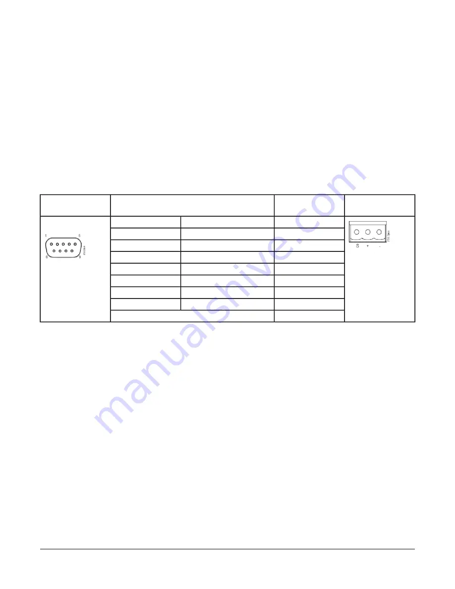
The FX30E/FX60E has two serial ports (Figure 10). Each
port has a Universal Asynchronous Receive Transmit
(UART) capable of operating up to 115,200 baud. The
left port is an RS-232 port that requires a DB-9 male plug
connector. The right port is a non-isolated RS-485 port
that uses two wires with a shield connection and a
screw-terminal connector plug.
Note:
A green receive LED and yellow transmit LED are
provided for each serial port. These LEDs are
located on the bottom board opposite of the serial
connectors (
Figure 7
). The LEDs are labeled on
the board (COM1, COM2) and are not visible with
the cover on.
RS-232 Port
An RS-232 serial port uses a DB-9 male connector and
always operates as COM1. You can use a standard DB-9
serial cable with this port. The FX30E/FX60E is a serial
Data Terminal Equipment (DTE) device, so connecting
another DTE device (computer) requires a null modem
cable. To connect the FX30E/FX60E to a Data
Communication Equipment (DCE) device (modem), use
a straight-through cable.
Table 4
provides the standard
serial DB-9 pinouts.
Table 4: Serial Port Pinouts
Base RS-485 Port
(COM2) Pinouts
DB-9 Plug Pin
Signal
Pinout References
1
Data carrier detect
DCD
DB-9 Plug (Male)
2
Receive data
RXD
3
Transmit data
TXD
4
Data terminal ready
DTR
5
Ground
GND
6
Data set ready
DSR
7
Request to send
RTS
8
Clear to send
CTS
9
Not used on the FX30E/FX60E
RS-485 Port
An RS-485 non-isolated port uses a 3-position, screw
terminal connector and always operates as COM2. Use
shielded 18-22 AWG wire for this connector (refer to the
Telecommunications Industry Association/Electronic
Industries Alliance [TIA/EIA-485 standard]). As shown in
Table 4, the screw terminals (from left to right) are shield,
plus (+), and minus (–).
RS-485 Biasing
The FX30E/FX60E's RS-485 port has a pair of 2-pin
jumpers that can be shorted with jumper blocks to provide
biasing
. When shipped from the factory, these pins are
not shorted and therefore, the RS-485 port is unbiased.
Biasing can improve RS-485 communications by
eliminating indeterminate idle states. When you install
two, 2-pin shorting blocks on the controller's RS-485 bias
jumper pins, the shorting blocks add two onboard 3.3K
ohm resistors into the controller's RS-485 circuit, as
follows:
•
from RS-485 plus (+) to 5 V
•
from RS-485 minus (-) to ground
Note:
Only one device on an RS-485 trunk should be
biased. Otherwise, undue loading of the circuit
may result with fewer devices supported.
Note:
RS-485 bias resistors are different than
termination resistors, externally installed at the
two physical ends of a daisy-chained RS-485
trunk, across the plus (+) and minus (-) terminals.
Termination resistors are typically 100 or 120 ohm
value resistors.
Note:
If termination resistors are used, RS-485 biasing
is typically required.
16
FX30E/FX60E Supervisory Controllers Installation Instructions


